Air dryer

An air dryer and cavity technology, which is applied in chemical instruments and methods, separation methods, dispersed particle separation, etc. Convenient, simple and compact structure, the effect of reducing the number

Pending Publication Date: 2018-01-19
江苏江海船舶设备制造有限公司
2 Cites 0 Cited by

AI-Extracted Technical Summary

Problems solved by technology

The double plug valve is a key component to control the switching of the working conditions of the two working towers. In actual use, due to the damage of the internal rubber of the double plug valve or the failure of the spring, it is easy to cause air leakage in the air dryer and a loud exhaust sound; and because It has a complex double-tower structure, and the maintenance workload is relativ...

Abstract

The invention discloses an air dryer which comprises a shell and an inner container, wherein a sealed cavity is formed between the shell and the inner container; the inner container is further filledwith a desiccant; an air inlet, an air outlet and a waste outlet are formed in the inner container; the air inlet is communicated with an air inlet channel; an electromagnetic valve a is fixedly mounted on the air inlet channel; an oil filter element is mounted on the air inlet channel; an oil collection channel is fixedly connected with the lower end part of the air inlet channel; an oil collection cup is connected with the lower end part of the oil collection channel; the oil collection cup is fixedly mounted at the lower end part of the shell. Due to addition of the oil filter element, fineoil droplets in the air can form large oil droplets on a filtering net when contacting the oil filter element, and is further discharged out from the oil collection channel, large oil droplets discharged out from the oil collection channel can be collected by the oil collection cup, and thus the environment outside the air outlet can be prevented from pollution of discharged oil.

Application Domain

Dispersed particle filtration

Technology Topic

Air dryerElectromagnetic valve +5

Image

  • Air dryer

Examples

  • Experimental program(1)

Example Embodiment

[0016] The following specific examples illustrate the implementation of the present invention. Those skilled in the art can easily understand other advantages and effects of the present invention from the content disclosed in this specification.
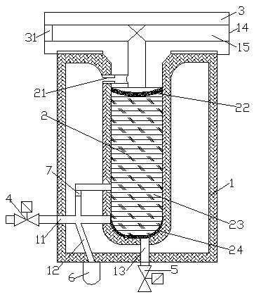
[0017] Such as figure 1 Shown is a schematic diagram of the overall structure of the present invention. An air dryer includes a housing 1 and an inner liner 2. A closed cavity is formed between the housing 1 and the liner 2, and the inner liner 2 is also placed inside. Agent 23, the inner tank 2 is provided with an air inlet, an air outlet and a waste discharge port, the air inlet is connected with an air inlet passage 11, and a solenoid valve a4 is fixedly installed on the air inlet passage 11, and An oil filter element 7 is installed on the intake passage 11, an oil collecting passage 12 is also fixedly connected to the lower end of the intake passage 11, an oil collecting cup 6 is connected to the lower end of the oil collecting passage 12, and the oil collecting cup 6 It is fixedly installed at the lower end of the housing 1. In the present invention, by adding the oil filter element 7, when small oil droplets in the air touch the oil filter element 7, large oil droplets are formed on the filter screen, and then discharged from the oil collecting channel 12, and the large oil droplets discharged from the oil collecting channel 12 are collected The oil cup is collected to prevent the discharged oil from polluting the environment outside the exhaust port.
[0018] An orifice 21 is also provided between the air outlet and the cavity, and the air outlet and the cavity are communicated through the orifice 21.
[0019] The exhaust port is connected with an exhaust gas passage 13, a solenoid valve b5 is fixedly installed on the exhaust gas passage 13, a filter 22 is fixedly installed at the air outlet of the inner tank 2, and the waste discharge port of the inner tank 2 A screen 24 is fixedly installed. In the present invention, a screen 24 is installed at the waste outlet of the inner tank 2. The screen 24 has a ventilation function and can prevent the desiccant 23 from being lost through the waste outlet; a filter 22 is installed at the air outlet. 22 also has a ventilation function, which is mainly used to isolate the desiccant 23 from the external passage.
[0020] The inner liner 2 is fixedly installed with a gland 3 at the air outlet, the gland 3 is provided with an underpass 15, the underpass 15 is provided with an exhaust port 14, and the underpass 15 is connected to the air outlet. The longitudinal section of the inner liner 2 is in the shape of "U", the longitudinal section of the gland 3 and the underpass 15 is in the shape of "T", and the exhaust port 14 has two and is located at the two lateral ends of the underpass 15 respectively. Part, the inner liner 2 is connected with the gland 3 through a thread at its outlet, a dew point indicator is installed in the underpass 15, and a check valve is installed at the outlet 14 of the gland 3 . The invention adopts a built-in double-layer structure, has a simple and compact structure, reduces the number of peripheral parts, can effectively reduce the number of spare parts, makes maintenance convenient, occupies a small space, and can meet the actual demand for compressed air drying.
[0021] A closed cavity is formed between the outer shell 1 and the inner liner 2, and the air outlet is respectively communicated with the outside and the cavity of the outer shell 1. Therefore, during use, when the air inlet is opened and the waste outlet is closed, the moisture is compressed Air can enter the liner through the air inlet and become dry air after being dried 23 by the desiccant in the liner 2. Part of the dry air can be discharged from the outer shell through the air outlet, and the other part will flow into the shell 1 and In the cavity between the inner tank 2; and when the air inlet is closed and the waste discharge port is opened, the above-mentioned dry air stored in the cavity will be flushed back into the inner tank 2, and the desiccant in the inner tank 2 The water molecules in 23 are taken away from the waste outlet, so as to realize the regeneration of the desiccant.
[0022] The above-mentioned embodiments are only preferred embodiments of the present invention, and do not limit the technical solutions of the present invention. As long as they are technical solutions that can be implemented on the basis of the above-mentioned embodiments without creative work, they shall be regarded as falling into the patent of the present invention. Within the scope of protection of the rights.

PUM

no PUM

Description & Claims & Application Information

We can also present the details of the Description, Claims and Application information to help users get a comprehensive understanding of the technical details of the patent, such as background art, summary of invention, brief description of drawings, description of embodiments, and other original content. On the other hand, users can also determine the specific scope of protection of the technology through the list of claims; as well as understand the changes in the life cycle of the technology with the presentation of the patent timeline. Login to view more.

Similar technology patents

Animal blood collector

Owner:山东省动物疫病预防与控制中心

Clutch control system with emergency pattern

Owner:TIANJIN SANTROLL ELECTRIC AUTOMOBILE TECH CO LTD

Low-noise damping exhaust silencer

Owner:TIANJIN QIXING PRECISION MACHINERY

Classification and recommendation of technical efficacy words

  • reduce the number
  • Simple and compact structure

Method and system for detecting single-plate on position

ActiveCN1912641Areduce the numberReliable presence detection
Owner:HUAWEI TECH CO LTD

Multiband matching circuit, radio frequency circuit, antenna system and mobile terminal

InactiveCN106571788AReduce the difficulty of debuggingreduce the number
Owner:QINGDAO HISENSE MOBILE COMM TECH CO LTD

Motor rotor automatic assembling machine

Owner:DONGGUAN WORLD PRECISION MACHINERY

Ultra-wide frequency band multi-band array antenna

ActiveCN104269649ASimple and compact structureFlexible arrangement
Owner:GUANGDONG BROADRADIO COMM TECH

Leg of multi-legged walking robot

InactiveCN102530121ASimple and compact structureFlexible and reliable walking
Owner:ZHEJIANG UNIV
Why Eureka
Try Eureka