Mechanical structure of novel sensor and novel sensor

A conical mirror and refractive index technology, which is applied to direction finders using electromagnetic waves, direction/deviation to determine the direction of electromagnetic systems, etc., can solve the problem of decreased reliability and accuracy of position information, failure to give position information in real time, and real-time positioning. and other problems, to achieve the effect of easy maintenance and replacement, compact structure and simple structure

Active Publication Date: 2018-01-19
DALIAN UNIV OF TECH
View PDF3 Cites 4 Cited by
  • Summary
  • Abstract
  • Description
  • Claims
  • Application Information

AI Technical Summary

Problems solved by technology

Among them, the imaging sensor can directly image the sky area with a large field of view with the help of a wide-angle lens, but in order to measure the polarization mode, it is necessary to obtain multiple sky images in different polarization directions, which often requires multiple shots by one camera or multiple cameras at the same time. There are two ways to realize the shooting, the former way is not real-time, and the latter way will lead to complex system structure; the point source sensor is based on the integration of multi-channel polarized light sensitive elements and photodiodes, and the polarized light at a certain point in the sky Real-time detection can be achieved. Due to the multi-channel sensor, the structure of the sensor is complicated and the navigation accuracy is limited.
[0005] The patent number disclosed in the prior art: (CN 103115623A), the positioning technology with polarized light navigation technology as the core, cannot realize real-time positioning. This technical solution needs to measure the maximum polarization direction of the polarized light angle sensor at different times in order to calculate the latitude and longitude , at the same time implies a requirement that the position of the carrier cannot be changed in the two measurements before and after
This technology cannot provide real-time location information, and when the time interval is too short, the reliability and accuracy of the location information will be significantly reduced

Method used


Image

  • Mechanical structure of novel sensor and novel sensor
  • Mechanical structure of novel sensor and novel sensor
  • Mechanical structure of novel sensor and novel sensor

Examples


Embodiment Construction

[0026] In order to make the purpose, features and advantages of the present application more obvious and understandable, the technical solutions in the embodiments of the present application will be clearly and completely described below in conjunction with the drawings in the embodiments of the present application. Obviously, the described The embodiments are only some of the embodiments of the present application, but not all of them. Based on the embodiments in this application, all other embodiments obtained by those skilled in the art without making creative efforts belong to the scope of protection of this application.

[0027] Those skilled in the art can understand that terms such as "first" and "second" in this application are only used to distinguish different devices, modules or parameters, etc., neither represent any specific technical meaning, nor represent the inevitable relationship between them. logical order.

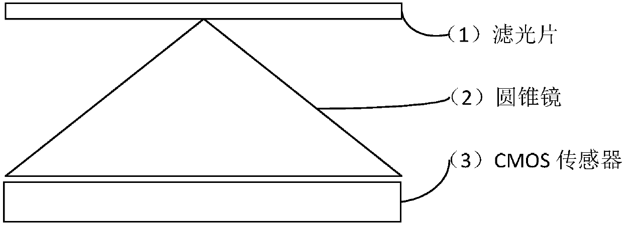
[0028] figure 1 The structure and arrangement o...


PUM


Abstract

The invention discloses a mechanical structure of a novel sensor and the novel sensor. The sensor can be used for pose control of an aircraft and generally belongs to a solar sensor. Specifically, thesensor is a novel imaging-type polarization light navigation sensor. The sensor comprises a filtering sheet, a cone mirror and a CMOS sensor. The refractive index of materials of the cone mirror andthe included angle between the cone face and the bottom are obtained through strict design and calculation. The CMOS sensor with quite high resolution is used for receiving polarization light penetrating through the cone mirror. The sensor is simple in structure, high in timeliness, and high in measurement precision and has favorable application prospects in polarized light azimuth angle measurement and polarized light navigation.

Description

technical field [0001] The invention belongs to the field of sensor structure design, in particular to a polarized light azimuth measurement sensor based on the structure design of a conical mirror. Background technique [0002] The current navigation system can be divided into non-autonomous navigation technology represented by satellite navigation, and autonomous navigation technology such as inertial navigation, geomagnetic navigation and celestial navigation. After a long period of development, satellite navigation technology is relatively mature, and it is the most widely used, with high navigation accuracy and global positioning capabilities, but it is susceptible to interference and easy to lose signals. Inertial navigation has strong autonomy and high precision, but its errors accumulate over time, so frequent calibration is required. Geomagnetic navigation has the advantages of no error accumulating over time and strong concealment, but it is easily disturbed by ex...

Claims


Application Information

Patent Timeline
Patent Type & Authority Applications(China)
IPC IPC(8): G01S3/782
Inventor 张然樊元义褚金奎吴晨奇
Owner DALIAN UNIV OF TECH
Why Eureka
Try Eureka