Agreement structure for friction nano generator-used friction layer material surface roughness and manufacturing method thereof

A nanogenerator and surface roughening technology, applied in the direction of triboelectric generators, can solve the problems of cumbersome process, high preparation cost, long time consumption, etc., and achieve the effect of large contact area

Active Publication Date: 2018-01-23
HARBIN INST OF TECH SHENZHEN GRADUATE SCHOOL
View PDF3 Cites 14 Cited by
  • Summary
  • Abstract
  • Description
  • Claims
  • Application Information

AI Technical Summary

Problems solved by technology

[0008] In view of the problems existing in the prior art, the purpose of the present invention is to solve the problems of high cost, time-consuming and cumber

Method used


Image

  • Agreement structure for friction nano generator-used friction layer material surface roughness and manufacturing method thereof
  • Agreement structure for friction nano generator-used friction layer material surface roughness and manufacturing method thereof
  • Agreement structure for friction nano generator-used friction layer material surface roughness and manufacturing method thereof

Examples


Embodiment 1

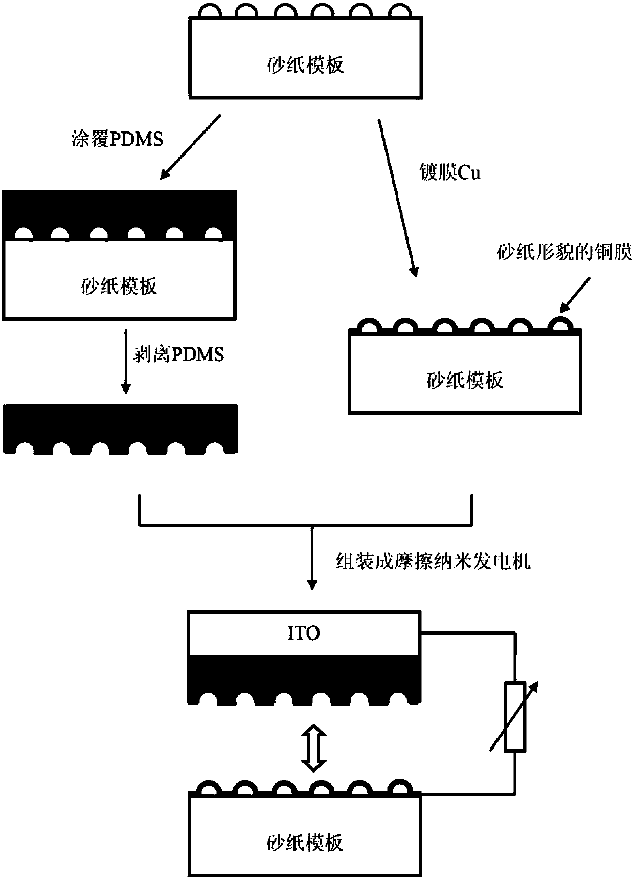
[0047] refer to figure 1 A schematic diagram of the preparation process, a method for preparing a friction layer material with a roughened surface for a friction nanogenerator, including:

[0048] step 1):

[0049] Step (1a), first cut the 10,000-mesh sandpaper into 3cm×3cm, then ultrasonically clean the sandpaper with alcohol, and finally dry it for later use;

[0050] Step (1b), first prepare the PDMS solution: first weigh the PDMS preparation raw material prepolymer A and crosslinking agent B according to the mass ratio of 10:1, and then put them on a magnetic stirrer and stir for 15-60 minutes to make the two components fully well mixed;

[0051] Step (1c), put the uniformly mixed PDMS solution into a vacuum degassing device to remove air bubbles in the mixed solution. Then use the spin-coating method to spin-coat the PDMS solution on the spare sandpaper, then put the sandpaper spin-coated with PDMS on a heating table at 80-250°C, heat it for 15-60min, take it off and c...

Embodiment 2

[0060] Different from Example 1, only the sandpaper mesh number of step (1a) is changed to be 12000 mesh, and other steps remain unchanged. Since the larger the mesh number of the sandpaper is, the smaller the structural size is, and the output performance of the triboelectric nanogenerator is better.

Embodiment 3

[0062] The difference from Example 1 is that the sandpaper template in step (1a) is changed to a photolithographic silicon template, and other steps remain unchanged. As the feature size of the photolithographic template pattern is reduced, the device performance is better. (Whether it is a fine silicon template or a simple sandpaper template, as long as the size of the surface is smaller, the performance will be better)


PUM

PropertyMeasurementUnit
Thicknessaaaaaaaaaa
Thicknessaaaaaaaaaa
Thicknessaaaaaaaaaa

Abstract

The invention belongs to the field of material micro surface processing, and particularly relates to an agreement structure for friction nano generator-used friction layer material surface roughness and a manufacturing method thereof. The method uses a simple sand paper template, spin coating of PDMS onto the rough surface of the sand paper is carried out, and after stripping, a PDMS film with a pattern surface complementary with the shape of the sand paper is manufactured; and on the other hand, a copper film with a small thickness is directly evaporated on the sand paper surface through a thermal evaporation and film coating mode, and thus, a copper friction material with a rough surface and a reproduced sand paper shape is manufactured. The two positive and negative friction layer materials used by the friction nano generator are manufactured, and the material has a surface with a pattern complementary with the shape of the sand paper and also has a surface with the sand paper shapepattern. More importantly, templates with the same specifications are adopted for manufacturing, the sizes of the surface shape patterns are almost the same, the shapes are complementary and can completely agree, and the actual contact area during the friction process is larger.

Description

technical field [0001] The invention belongs to the field of microscopic surface treatment of materials, and in particular relates to a fitting structure for roughening the surface of a friction nanogenerator friction material and a preparation method thereof. Background technique [0002] Due to a series of advantages such as light weight, low cost, simple preparation process, good stability, high energy conversion efficiency and long service life, triboelectric nanogenerators have broad application prospects in the field of power generation and mobile electronic devices. The working principle of the triboelectric nanogenerator is based on triboelectrification and electrostatic induction, in which the friction layer is the most important component, which mainly uses triboelectrification to generate static charges. For the friction layer material, after the contact surface of each friction separates, the amount of charge transferred per unit area and the actual contact area ...

Claims


Application Information

Patent Timeline
IPC IPC(8): H02N1/04
Inventor 汪桂根张绪武李桂钟韩杰才
Owner HARBIN INST OF TECH SHENZHEN GRADUATE SCHOOL
Why Eureka
Try Eureka