An all-motor-driven precision molding machine and its operating method

A molding, motor-driven technology, applied in glass pressing, glass molding, manufacturing tools, etc., can solve the problem of increasing system equipment cost, low response speed and controllable degree of freedom, mold clamping speed, position and forming force. The problem of low control accuracy

Active Publication Date: 2019-09-06
BEIJING INSTITUTE OF TECHNOLOGYGY
View PDF3 Cites 0 Cited by
  • Summary
  • Abstract
  • Description
  • Claims
  • Application Information

AI Technical Summary

Problems solved by technology

The optical material molding machine tool developed by thermoforming technology has already been commercialized; however, most of the molding mechanisms on the market use cylinders, which have problems such as low control accuracy of mold clamping speed, position and forming force. It directly affects the improvement of technical indicators such as surface accuracy and roughness of molded products; at the same time, the pneumatic drive needs to be equipped with an independent compressed air supply system, and additional air compressors, voltage stabilization and drying and filtering equipment are required, which increases the cost of system equipment; in addition The current molding machine is mainly controlled by PLC. Although its stability is relatively good, its computing power is far inferior to that of an industrial PC inserted into a motion control board, and its response speed and controllable degree of freedom are not high.

Method used


Image

  • An all-motor-driven precision molding machine and its operating method
  • An all-motor-driven precision molding machine and its operating method
  • An all-motor-driven precision molding machine and its operating method

Examples


Embodiment Construction

[0082] The technical solutions of the present invention will be clearly and completely described below in conjunction with the accompanying drawings. Apparently, the described embodiments are some of the embodiments of the present invention, but not all of them. Based on the embodiments of the present invention, all other embodiments obtained by persons of ordinary skill in the art without making creative efforts belong to the protection scope of the present invention.

[0083] The present invention will be described in further detail below through specific implementation examples and in conjunction with the accompanying drawings.

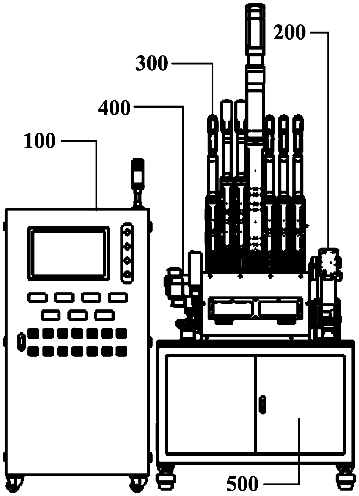
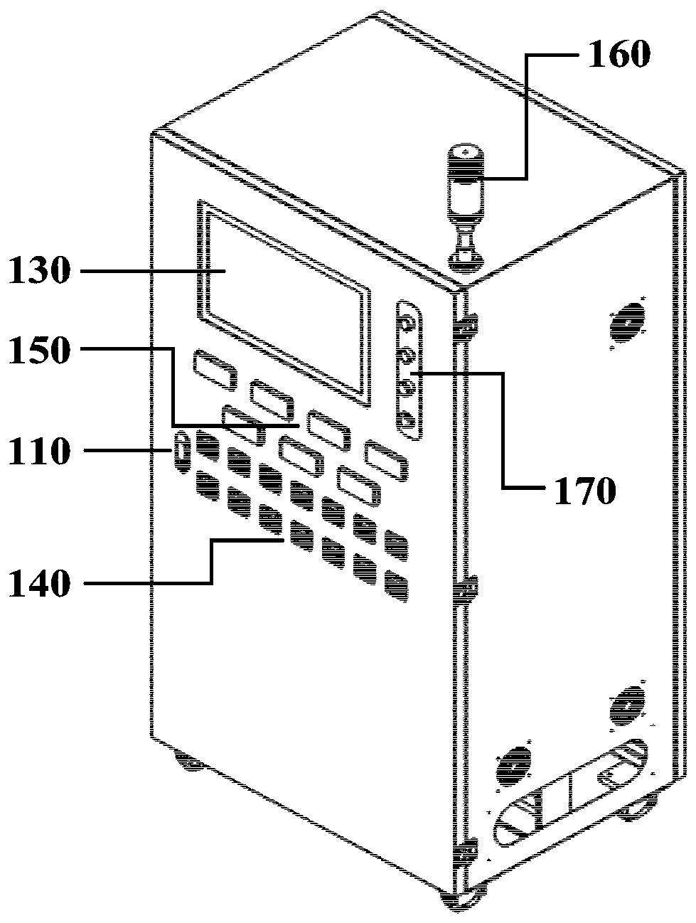
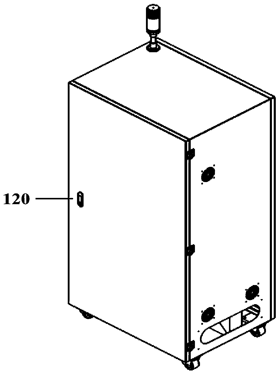
[0084] see figure 1 , figure 2 , the embodiment of the present invention provides an all-motor-driven precision molding machine, including a console 100, an input assembly 200, a molding machine main body 300, an output assembly 400, and a frame assembly 500; the console 100 and The feeding assembly 200, the molding machine main body 300, the di...


PUM


Abstract

Provided are a fully motor-driven precision compression molding machine and an operation method. The compression molding machine comprises a console (100) and a feeding component (200), a compression molding machine body (300), a discharging component (400), and a rack component (500). The feeding component is configured to feed a die and a preform into the compression molding machine body. The compression molding machine body is configured to process the preform. The compression molding machine body comprises a molding mechanism (310), a shift fork mechanism (340), a forming cabin (350), and nitrogen delivery ports (360). A plurality of nitrogen delivery ports is disposed outside the compression molding machine body for inputting nitrogen into the forming cabin to ensure that the nitrogen concentration exceeds a critical point after a certain period of time so as to form a protective atmosphere, thus preventing the preform and the die from being oxidized at high temperature. The discharging component is configured to deliver an assembly out of the compression molding machine body. The driving mode has high control precision and ease of operation.

Description

technical field [0001] The invention relates to the technical field of machine tool equipment, in particular to an all-motor-driven precision molding machine. Background technique [0002] As we all know, there is a huge market demand for optical lenses such as spherical, aspherical, and free-form surfaces, optical microstructures such as microprism arrays, microlens arrays, and micro-groove arrays, and optical devices with complex curved surfaces such as Fresnel lenses. It is made of optical materials such as optical glass and infrared glass. At present, optical device processing can be divided into the following three categories: [0003] The first category is the use of mechanical processing, mainly including single-point diamond turning, ultra-precision grinding and various polishing processes. Machining methods can process most optical components, and can achieve extremely high processing accuracy. [0004] The second category is the use of photolithography processin...

Claims


Application Information

Patent Timeline
Patent Type & Authority Patents(China)
IPC IPC(8): C03B11/00C03B11/16
Inventor 周天丰杜逸飞周琴梁志强刘志兵颜培焦黎解丽静王西彬蔡志敏
Owner BEIJING INSTITUTE OF TECHNOLOGYGY
Why Eureka
Try Eureka