A kind of dry etching equipment

A technology of dry etching and equipment, applied in the direction of circuits, discharge tubes, electrical components, etc., can solve the problems of shortening the production and maintenance cycle of the process chamber, poor thermal conductivity and mechanical strength, and affecting product yield, so as to prolong production and maintenance The cycle and processing method are simplified, and the effect of saving production and maintenance costs

Active Publication Date: 2019-10-11
WUHAN CHINA STAR OPTOELECTRONICS SEMICON DISPLAY TECH CO LTD
View PDF4 Cites 0 Cited by
  • Summary
  • Abstract
  • Description
  • Claims
  • Application Information

AI Technical Summary

Problems solved by technology

However, the thermal conductivity and mechanical strength of ceramic parts are poor, and the temperature control during the process is generally ≤80°C, otherwise the ceramic parts will have the risk of cracking; at the same time, it is easy to attach a large amount of process products, which will fall down when they accumulate a lot. Etching residue (etching residue) occurs in the product in the process, which affects the product yield and shortens the production maintenance cycle (PMcycle) of the process chamber

Method used


Image

  • A kind of dry etching equipment
  • A kind of dry etching equipment
  • A kind of dry etching equipment

Examples


Embodiment Construction

[0031] The following descriptions of various embodiments refer to the accompanying drawings to illustrate specific embodiments in which the present invention can be implemented.

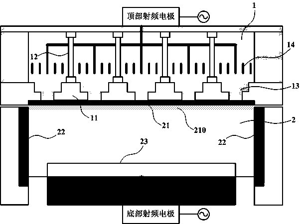
[0032] Please refer to figure 1 As shown, the embodiment of the present invention provides a dry etching equipment, including:

[0033] The process chamber formed by sealing the upper cavity 1 and the lower cavity 2 is used to perform various process reactions required for the dry etching process in the inductively coupled plasma mode;

[0034] The upper cavity 1 is provided with a plurality of skeletons 11 and suspension columns 12 for supporting the skeletons 11, and spaces are formed between the skeletons 11 for placing non-conductive dielectrics 13;

[0035] An antenna coil 14 is also arranged in the upper cavity 1 for forming an alternating current, and an alternating magnetic field or an electric field is induced by the alternating current and transmitted to the lower cavity 2 to form a high c...


PUM


Abstract

The invention provides dry etching equipment, which comprises a process chamber formed by sealing an upper chamber and a lower chamber and used for carrying out various process reactions required by adry etching process under an inductively coupled plasma mode. The upper chamber is internally provided with a plurality of skeletons and suspension columns for supporting the skeletons; a space is formed between two adjacent skeletons and is used for placing a non-conductive current-inducing body; the upper chamber is also internally provided with an antenna coil for forming an alternating current; and an alternating magnetic field or an electric field is induced by the alternating current and is transmitted to the lower chamber to form high-concentration plasma under the inductively coupledplasma mode. The dry etching equipment also comprises a top plate, which is arranged between the upper chamber and the lower chamber and is tightly attached to the current-inducing bodies. The top plate is an aluminum anode member plated with an anode oxide film. The top plate contacted with the plasma is designed to be the aluminum anode member plated with the anode oxide film, thereby improvingmechanical property and heat-conducting property of the top plate, enabling the top plate to be able to realize high temperature control, solving the problem of etching residual caused by product attachment and prolonging production maintenance cycle.

Description

technical field [0001] The invention relates to the technical field of screen display, in particular to a dry etching device. Background technique [0002] In the LTPS&OLED process, the Gate line (GE film layer, also known as gate electrode) and Source-Drainline (SD film layer, also known as gate electrode or source-drain electrode) of the metal layer have a film structure of molybdenum film (Mo) Or molybdenum-tungsten alloy film (MoW), and laminated film of titanium film, aluminum film and titanium film (Ti / Al / Ti), etc. In order to meet the critical dimension loss (CD loss) requirements of high-resolution products, the DryEtch process (dry etching process) of ICP Mode (Inductively Coupled Plasma Mode, inductively coupled plasma mode) is usually used to transfer the pattern on the mask onto the membrane layer. [0003] In the traditional ICP Mode dry etching machine equipment, the top plate of the process chamber (Process Chamber) is a ceramic part, and its insulation can ...

Claims


Application Information

Patent Timeline
Patent Type & Authority Patents(China)
IPC IPC(8): H01J37/02H01J37/30H01J37/305
Inventor 肖文欢
Owner WUHAN CHINA STAR OPTOELECTRONICS SEMICON DISPLAY TECH CO LTD
Why Eureka
Try Eureka