Multi-layer structure-based millimeter wave array antenna

A multi-layer structure and array antenna technology, which is applied in the field of antenna and wireless communication, can solve the problems of unfavorable array antenna miniaturization and high gain design, shorten the length of the horn opening, and large antenna size, so as to shorten the length of the horn antenna and avoid parasitic Radiation, effect of reducing insertion loss

Inactive Publication Date: 2018-01-26
XIDIAN UNIV
View PDF3 Cites 18 Cited by
  • Summary
  • Abstract
  • Description
  • Claims
  • Application Information

AI Technical Summary

Problems solved by technology

[0004] For example, in 2014, IEEE Transactions on Antenna and Propagation published an article titled "300-GHz Step-Profiled Corrugated Horn Antennas Integrated in LTCC" by Takuro Tajima et al., which disclosed a millimeter-wave rectangular horn antenna that integrates waveguides through substrates. Technology, using air cavity and metallized through-hole array to form a hollow feed waveguide and a rectangular horn structure in the dielectric layer, which reduces the dielectric loss in the millimeter-wave frequency band and improves the radiation efficiency of the antenna, so that the gain of the horn antenna reaches 18dBi , while shortening the length of the horn opening, the overall size of the antenna is 5λ×5λ×2.8λ, but the size of the antenna is still large and the gain is low, which is not conducive to the miniaturization and high-gain design of the array antenna, where λ is the wavelength in the air

Method used


Image

  • Multi-layer structure-based millimeter wave array antenna
  • Multi-layer structure-based millimeter wave array antenna
  • Multi-layer structure-based millimeter wave array antenna

Examples


Embodiment Construction

[0022] The present invention will be further described below in conjunction with the accompanying drawings and specific embodiments.

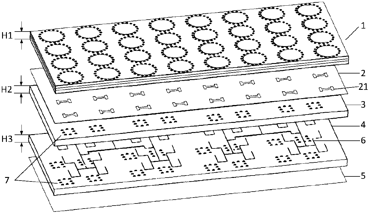
[0023] refer to figure 1 , a millimeter-wave array antenna based on a multilayer structure, including 4×8 antenna units 1, a first dielectric plate 3 and a second dielectric plate 4 stacked up and down, the thickness of the antenna unit 1 is H1=1.248mm, The thickness of the first dielectric board is H2=0.096mm, the thickness of the second dielectric board is H3=0.48mm, the upper surface of the first dielectric board 3 is printed with an internal grounding plate 2, and the second An external grounding plate 5 is printed on the lower surface of the dielectric plate 4, and 4×8 radiation slots 21 are etched on the internal grounding plate 2, such as image 3 As shown, the antenna unit 1 is fixed on the internal ground plate 2, and is located directly above the radiation slot 21, as Figure 5 As shown, a feed network 6 is provided between the firs...


PUM


Abstract

The invention proposes a multi-layer structure-based millimeter wave array antenna. By the multi-layer structure-based millimeter wave array antenna, the gain is improved, and meanwhile, the miniaturization of the millimeter wave array antenna is achieved. The multi-layer structure-based millimeter wave array antenna comprises (m*n) antenna units, a first dielectric plate and a second dielectric plate, wherein the first dielectric plate and the second dielectric plate are vertically laminated, an internal grounding plate is printed on an upper surface of the first dielectric plate, an externalgrounding plate is printed on a lower surface of the second dielectric plate, (m*n) radiation gaps are etched in the internal grounding plate, the antenna units are fixed on the internal grounding plate and are arranged right above the radiation gaps, a feeding network is arranged between the first dielectric plate and the second dielectric plate and is used for performing coupling feeding on theantenna units, each antenna unit comprises a multi-layer dielectric plate, a metal plate is printed on an upper surface of each layer of dielectric plate, a round opening is formed in a plane centerof each layer of metal plate, and adjacent metal plates are connected via a metal through hole encircling an outer side of the round opening so as to form a round horn structure of which a caliber surface is gradually increased from bottom to top.

Description

technical field [0001] The invention belongs to the technical field of antennas, and relates to a millimeter-wave array antenna, in particular to a millimeter-wave array antenna based on a multi-layer structure, which can be used in wireless communication fields such as vehicle-mounted devices. Background technique [0002] With the rapid development of modern wireless communication systems worldwide, the requirements for antennas are getting higher and higher. For example, radar antennas generally require strong directivity, high gain, and small size. If a single antenna cannot meet the requirements, an array antenna needs to be built. Array antennas are a common form of antenna found in modern radar and communication systems. In array antenna design, gain and size are important performance indicators. Higher gain will directly increase the operating distance; the larger the aperture size, the higher the antenna gain, but the larger the space required to install the anten...

Claims


Application Information

Patent Timeline
Patent Type & Authority Applications(China)
IPC IPC(8): H01Q1/48H01Q1/50H01Q21/06H01Q21/18
Inventor 董刚余森杨银堂
Owner XIDIAN UNIV
Why Eureka
Try Eureka