Flow-dividing annular micro-channel radiator

A radiator and micro-channel technology, applied in the field of new micro-channel radiators, can solve the problem of uneven flow distribution, achieve good application prospects, improve uneven flow distribution, and improve the overall heat transfer capacity and heat transfer limit.

Active Publication Date: 2018-02-02
SICHUAN UNIV
View PDF4 Cites 19 Cited by
  • Summary
  • Abstract
  • Description
  • Claims
  • Application Information

AI Technical Summary

Problems solved by technology

[0004] The purpose of the present invention is to provide a new type of micro-channel heat dissipation structure for the defects existing in the existing shunt-type micro-channel heat sink, improve the problem of uneven flow distribution, strengthen the heat dissipation capacity, and increase the heat dissipation limit

Method used


Image

  • Flow-dividing annular micro-channel radiator
  • Flow-dividing annular micro-channel radiator
  • Flow-dividing annular micro-channel radiator

Examples


Embodiment 1

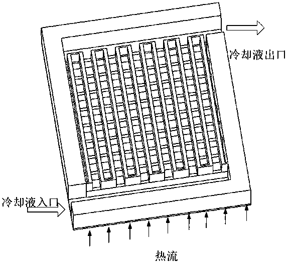
[0026] What this embodiment described is a split-type microchannel heat sink with multiple inlets and single outlets, such as figure 2 As shown, it consists of a circular micro rib 1 , a circular flow distribution structure 2 and a cover plate 3 .

[0027] see image 3 , the circular micro-rib 1 includes a primary distribution channel 1-1, an annular micro-rib 1-2 and a positioning hole 1-3. The material of the micro-rib 1 is first considered to be a metal material with good thermal conductivity, and its bottom surface is bonded to the heating element through thermal silica gel or thermal grease. The cooling working fluid enters the secondary distribution channel from the annular primary distribution channel 1-1. The height of the annular micro-ribs 1-2 and the spacing of the micro-ribs are on the order of millimeters or microns to increase the heat exchange area, and the specific size is determined according to actual needs.

[0028] see Figure 4 , the circular distribu...

Embodiment 2

[0032] This embodiment is basically the same as Embodiment 1, see Figure 7 The difference is that: the water inlet and outlet are in the form of single inlet and single outlet, which reduces the number of external pipes connected to the heat sink; in addition, an inlet and outlet water structure layer is added to improve the uneven distribution of the first flow caused by the single inlet structure.

[0033] The circular micro ribs 1 in this embodiment are the same as those in the first embodiment.

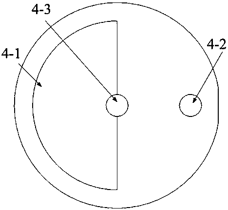
[0034] see Figure 8 , the circular distribution structure 2 includes an inlet water flow channel 2-1, an outlet water flow channel 2-2, a cover plate 2-3, a water outlet channel 2-4 and a positioning pin 2-5. The size of the shunt structure 2 is smaller than that of the circular micro-rib 1 to form an annular channel as a primary annular shunt channel. The cooling working fluid enters the water outlet structure layer 4 through the water outlet channels 2-4.

[0035] see Fig...


PUM


Abstract

The invention relates to a flow-dividing annular micro-channel radiator, which is mainly composed of a circular micro-rib plate, a circular flow dividing structure and a cover plate. The special flowdividing structure of the radiator is formed by annular micro-channels on the micro-rib plate and flow dividing channels on the flow dividing structure. The diameter of the circular flow dividing structure is less than that of the circular micro-rib plate, and an annular channel formed by the circular flow dividing structure and the circular micro-rib plate serve as a primary flow dividing channel, thereby effectively solving a problem of uneven primary flow dividing caused by a stagnation effect of a cooling working medium at the tail end of the flow dividing channel. Secondary flow dividingchannels are of a gradually shrinking structure, which can also weaken the influences of fluid stagnation inside the flow dividing channel and increase the uniformity of flow distribution between overflowing channels. The flow-dividing annular micro-channel radiator further improves the problem of nonuniform flow distribution on the basis of reserving advantages of the micro-channel flow dividingstructure, and has high heat exchange capacity and heat exchange limit. The flow-dividing annular micro-channel radiator is compact in structure and good in heat exchange capacity, and has excellent application prospects in the aspect of cooling for high heating equipment such as electronic chips, lasers and rectifiers.

Description

technical field [0001] The invention relates to a novel micro-channel heat sink, in particular to an improved annular micro-channel heat sink with a shunt structure, which can be used for cooling high heat-generating devices such as electronic chips, high-power LEDs and lasers. Background technique [0002] Since the 21st century, with the rapid development of high-tech fields, the integration, miniaturization and heating power of some devices and equipment have increased year by year. Increase. For example, on spacecraft, with the application of laser technology and the development of highly integrated electronic chips, the heat flux that needs to be cooled has reached 1 MW / m 2 above. In the field of nuclear energy applications, the tokamak device EAST developed in my country, the first wall divertor, passive plate, limiter, etc. are directly affected by the high temperature of the plasma, and the heat flux density on the target plate can reach 4MW / m 2 . For such a high...

Claims


Application Information

Patent Timeline
Patent Type & Authority Applications(China)
IPC IPC(8): H01L23/473H01S5/024
CPCH01L23/473H01S5/02423
Inventor 唐继国孙立成刘洪涛鲍静静莫政宇谢果
Owner SICHUAN UNIV
Why Eureka
Try Eureka