Positioning device and method for pipeline detection

A technology of pipeline detection and positioning device, applied in pipeline system, navigation through velocity/acceleration measurement, mechanical equipment, etc., can solve the problems of inability to apply long-distance pipeline detection, inability to guarantee measurement accuracy, and impact on measurement accuracy, and achieve a reduction in Cost and energy consumption, ensure stability, improve the effect of measurement accuracy

Inactive Publication Date: 2018-02-06
哈尔滨航士科技发展有限公司 +3
View PDF7 Cites 31 Cited by
  • Summary
  • Abstract
  • Description
  • Claims
  • Application Information

AI Technical Summary

Problems solved by technology

[0004] In the prior art, the method of only using the relative position information recorded by the odometer to locate the internal defects of the pipeline will cause the positioning error to accumulate with the length of the detected pipeline due to the slippage of the odometer, and can only detect short-distance pipelines each time, which cannot be applied to Long-distance pipeline detection; it is only a positioning method for error correction of the inertial measurement module (three-axis gyroscope and three-axis accelerometer), and does not correct the direction angle error of the pipeline detection and positioning system, which makes the low-cost inertial measurement module in The measurement accuracy cannot be guaranteed wh

Method used


Image

  • Positioning device and method for pipeline detection
  • Positioning device and method for pipeline detection
  • Positioning device and method for pipeline detection

Examples


specific Embodiment approach 1

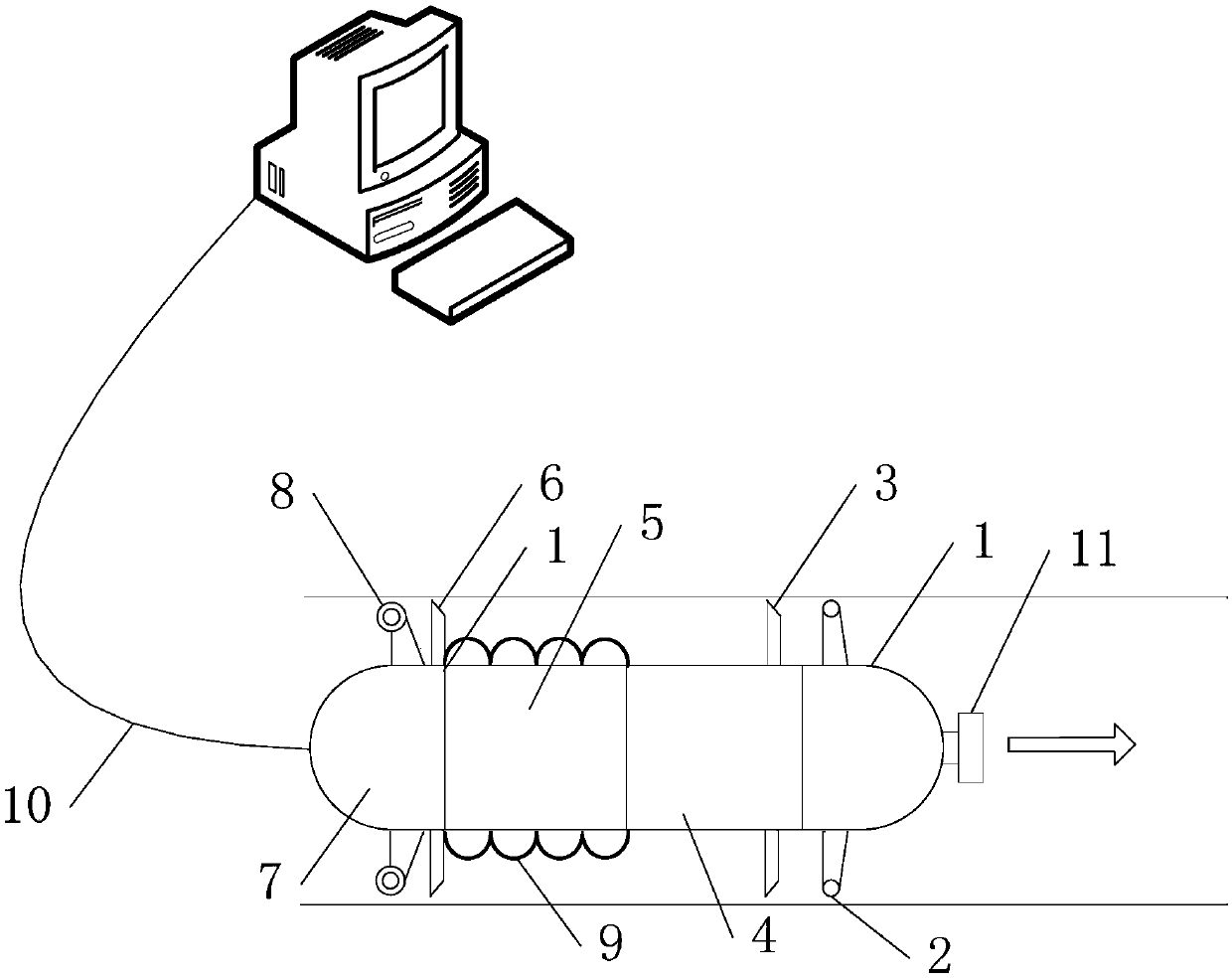
[0056] Specific Embodiment 1: Combining figure 1 and figure 2 Describe this embodiment, a positioning device for pipeline detection in this embodiment, the specific structure is as follows figure 1 As shown, it includes: power supply module 1, two support wheels 2, first plastic sealing ring 3, inertial measurement module 4, data processing unit 5, second plastic sealing ring 6, data storage unit 7, odometer 8, magnetic flux Leak sensor 9 , communication cable 10 and magnetic tracking module 11 .

[0057] The power supply module 1, inertial measurement module 4, data processing module 5 and data storage module 7 are arranged in sequence from front to back, and are fixed as a whole by the first plastic sealing ring 3 and the second plastic sealing ring 6 outside.

[0058] The power supply module 1 provides electric energy for the positioning device for pipeline detection to ensure its normal operation.

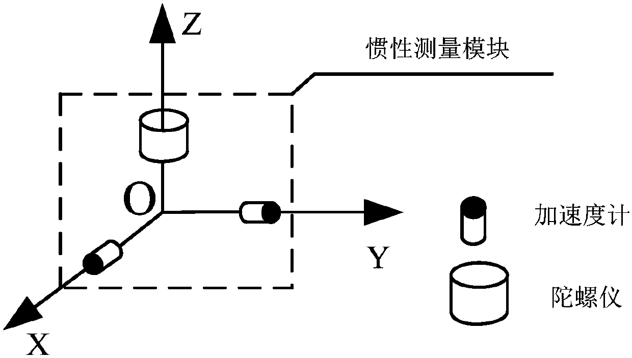
[0059] The structure of the inertial measurement module 4 is as figu...

specific Embodiment approach 2

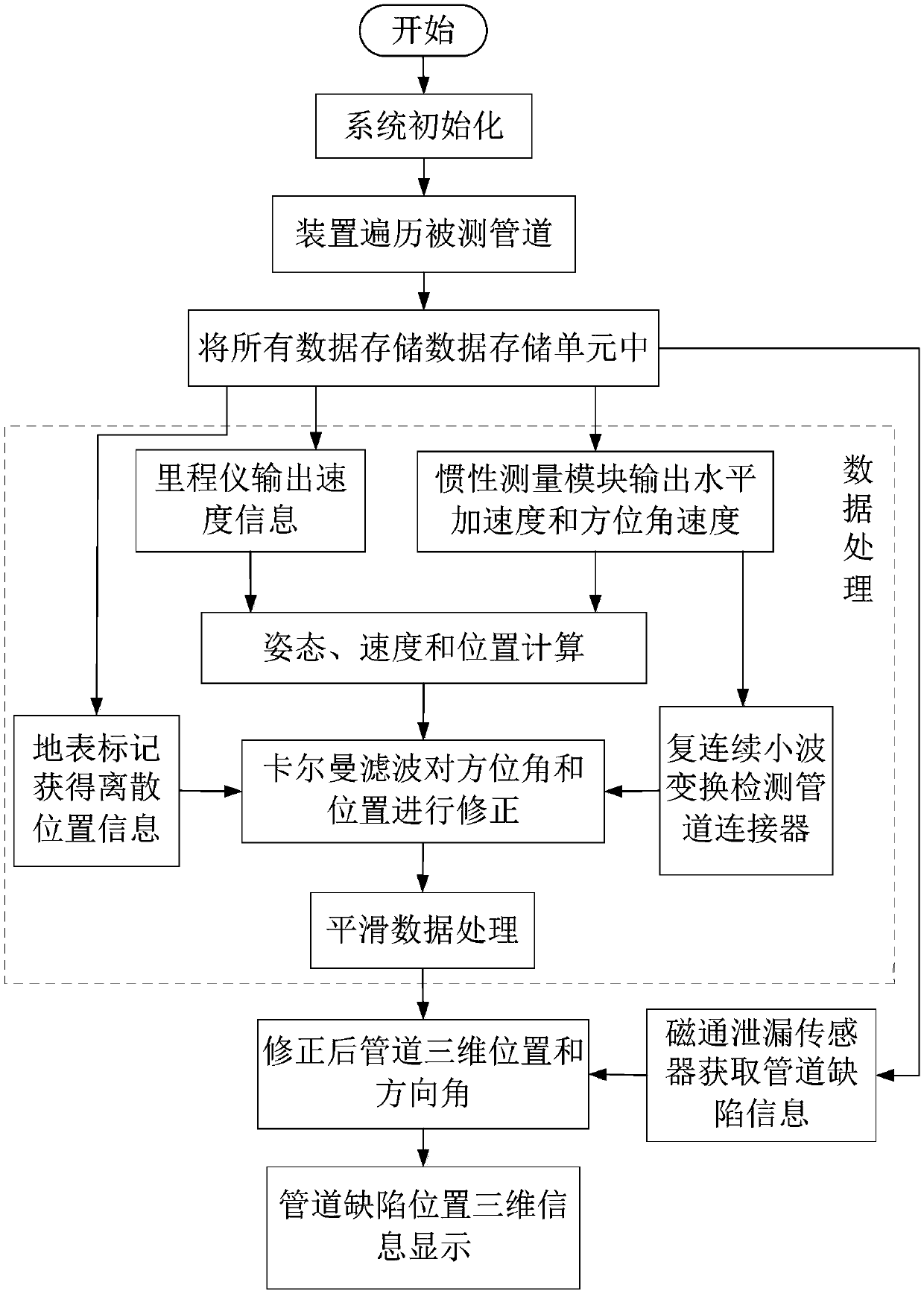
[0067] Specific Embodiment 2: Combining image 3 Describe this embodiment, the flow chart of the positioning method of this embodiment is as follows image 3 As shown, the specific steps include:

[0068] Step a, turn on the power supply module 1, and initialize the positioning device for pipeline detection;

[0069] Step b, make the positioning device for pipeline detection go through the pipeline once, and use the x-direction accelerometer, y-direction accelerometer, fiber optic gyroscope and odometer 8 to measure the roll angle, pitch angle, and orientation of the pipeline detection positioning device respectively Angle and axial velocity, using the magnetic flux leakage sensor 9 to detect pipeline defect information, simple processing of each measured value data through the data processing unit 5, and storing the processed data through the data storage unit 7;

[0070] Step c, combining the output data of the x-direction accelerometer, the y-direction accelerometer, the ...


PUM


Abstract

The invention relates to the technical field of pipeline geographic information measurement, in particular to a positioning device and method for pipeline detection. The problems that in the prior art, the precision is low, and remote measurement cannot be achieved are solved. The positioning device comprises a power supply module, two supporting rollers, a first plastic sealing ring, an inertia measuring module, a data processing unit, a second plastic sealing ring, a data storage unit, a mileage instrument, a flux leakage sensor, a communication cable and a magnetic tracking module. The inertia measuring module is composed of a gyroscope and two accelerometers; on the basis of the mileage instrument, and three-dimensional attitude angle, speed and position coordinate measurement inside the pipeline can be achieved. According to the positioning method, a complex continuous wavelet transform method is adopted for analyzing operating data of the inertia measuring module inside the pipeline, a pipeline connector is detected, and the method is used for correcting azimuth angle errors of the positioning device for pipeline detection. The device and method are applicable to detection ofland and underwater oil and gas pipelines.

Description

technical field [0001] The invention relates to the technical field of pipeline geographical information measurement, in particular to a positioning device and a positioning method for pipeline detection. Background technique [0002] Pipelines are not only an important carrier for the transportation of various onshore and underwater oil and gas resources, but also the fastest, economical and reliable transportation method. However, because most pipelines are buried underground or under the seabed with a certain depth, and underground pipelines are easily affected by terrain changes caused by man-made excavations and natural disasters, underwater pipelines have long been damaged by seawater corrosion, tidal stress, and even the impact of underwater shipwrecks. . In addition, with the aging of early laid pipelines, oil and gas leakage will also occur in severe cases. This not only threatens the life and property safety of people on land, but also brings immeasurable losses ...

Claims


Application Information

Patent Timeline
IPC IPC(8): F17D5/02F17D5/00G01C21/16
CPCF17D5/02F17D5/00G01C21/16
Inventor 管练武宋玉寰高延滨何昆鹏王萌吴建锋陈强强陈兴邦丛晓丹
Owner 哈尔滨航士科技发展有限公司
Why Eureka
Try Eureka