Drill quenching mechanism

A technology for drilling and processing boxes, applied in quenching devices, furnaces, heat treatment equipment, etc., can solve the problems of low work efficiency, low cooling efficiency, easy to burn hands, etc., to improve work efficiency, ensure smooth progress, and ensure heating Effect

Inactive Publication Date: 2018-02-09
南通旭越光电科技有限公司
View PDF0 Cites 0 Cited by
  • Summary
  • Abstract
  • Description
  • Claims
  • Application Information

AI Technical Summary

Problems solved by technology

[0004] Existing quenching devices for lasts need to be heat-treated one by one, the work efficiency is low, and it is not suitable for mass production. After the surface of the drill bit is heated rapidly, it will be sprayed with quenching liquid a few seconds later to make the surface of the workpiece meet the corresponding hardness requirements, but The spray time is short, the cooling efficiency is low, and the operator is easy to burn his hands when taking the drill bit. Therefore, how to develop a drill bit quenching system that improves work efficiency, adapts to mass production, and has high quenching and cooling efficiency is imperative.

Method used


Image

  • Drill quenching mechanism
  • Drill quenching mechanism

Examples


Embodiment Construction

[0019] The following examples can enable those skilled in the art to understand the present invention more comprehensively, but the present invention is not limited to the scope of the described examples.

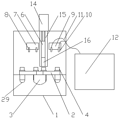
[0020] Such as figure 1 , figure 2 A drill bit quenching mechanism is shown, which is used for quenching the drill bit of an electric tool, including

[0021] A processing box 1, the processing box 1 is a rectangular parallelepiped hollow structure, and one side of the processing box 1 has an opening for feeding and taking materials.

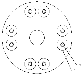
[0022] A quenching platform 2 installed in the box, the quenching platform 2 is a disc-shaped structure, and the quenching platform 2 is driven by a rotating motor 3 to rotate 360°.

[0023] A material placement unit installed on the upper end surface of the quenching platform 2, such as figure 2 As shown in the schematic diagram, it can be seen that the material placement unit includes several pairs of placement disk groups distributed ...


PUM


Abstract

The invention relates to a quenching mechanism for a drill bit, which comprises a processing box body; a quenching platform installed in the box body; The motor is driven to rotate; a heating unit and a cooling unit are arranged in the processing box and distributed along the quenching platform in turn. The guide plate is provided with a vertically oppositely extending heat-resistance-resistance baffle which is embedded and moves up and down. The advantage of the invention is that: through the mutual cooperation between the quenching platform, the placing plate group, the heating unit, and a cooling unit, the material feeding, material heating and material cooling processes can be simultaneously performed, and the cyclic work can be performed to realize batch production. production.

Description

technical field [0001] The invention relates to the field of electric tools, in particular to a drill quenching mechanism. Background technique [0002] In the 1960s, with the development of battery manufacturing technology, battery-type electric tools without power cords using nickel-cadmium batteries as power sources appeared. But at that time, due to the high price, the development was slow. By the mid-to-late 1970s, due to the reduction in battery prices and shortened charging time, this type of power tool was widely used in Europe, America, and Japan. Electric tools were originally made of cast iron, and then aluminum alloy was used as the casing. In the 1960s, thermoplastic engineering plastics were applied to electric tools, and realized double insulation of electric tools, ensuring the safety of electric tools. Due to the development of electronic technology, electronic speed control electric tools also appeared in the 1960s. This kind of electric tool uses thyri...

Claims


Application Information

Patent Timeline
IPC IPC(8): C21D9/22C21D1/667
CPCC21D9/22C21D1/667C21D9/0062
Inventor 徐吉华
Owner 南通旭越光电科技有限公司
Why Eureka
Try Eureka