
Tri-band bandpass microstrip filter with E-type resonators and stepped impedance resonators

A technology of microstrip filter and double-passband filter, applied in the direction of waveguide type devices, electrical components, circuits, etc., can solve the problems of inconvenient design and debugging, inflexible center frequency adjustment, complicated design, etc., to improve the sideband Suppression performance, convenient design and debugging, low insertion loss effect

Active Publication Date: 2018-02-09
YOSHIHIRO COMM EQUIP GRP CO LTD
View PDF4 Cites 2 Cited by
  • Summary
  • Abstract
  • Description
  • Claims
  • Application Information

AI Technical Summary

Problems solved by technology

[0004] The multi-passband filters in the existing literature often use ring resonators to form multi-passband filters, but the disadvantage is that they are very large
[0005] There is also a multi-passband filter designed by a stepped impedance resonator (SIR). The adjustment of the center frequency is inflexible. Since the change of the impedance ratio is limited, the distance between two adjacent passbands is smaller, resulting in an adjustable range of the center frequency. It is also relatively small, and the design of multiple passbands is more complicated
[0006] The traditional three-way microstrip filter feed adopts the tap type, which not only complicates the design, but also increases the size and volume of the entire filter, and it is inconvenient to design and debug
[0007] In order to improve the selectivity of the passband of the filter, SIR loading DGS is used in the existing literature to generate transmission zeros, but this method has a large loss on the signal and also increases the insertion loss

Method used


Image

  • Tri-band bandpass microstrip filter with E-type resonators and stepped impedance resonators
  • Tri-band bandpass microstrip filter with E-type resonators and stepped impedance resonators
  • Tri-band bandpass microstrip filter with E-type resonators and stepped impedance resonators

Examples


Embodiment Construction

[0031] The controllable three-pass band filter with compact bandwidth designed by the invention has adjustable pass bands and does not interfere with each other.

[0032] The present invention is described in more detail below in conjunction with accompanying drawing size:

[0033] The plate for making this three-pass band filter is a RogersRT / duroid5880 dielectric plate with a relative permittivity of 2.2 and a thickness of 0.78mm. The thickness of copper plating on the surface is 0.018mm. The metal ground plate under the dielectric substrate is made of copper material.

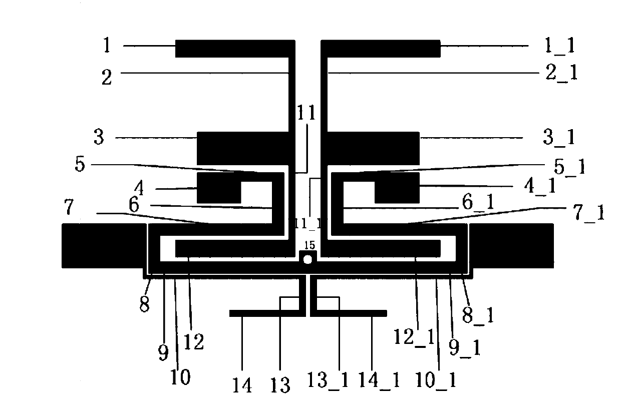
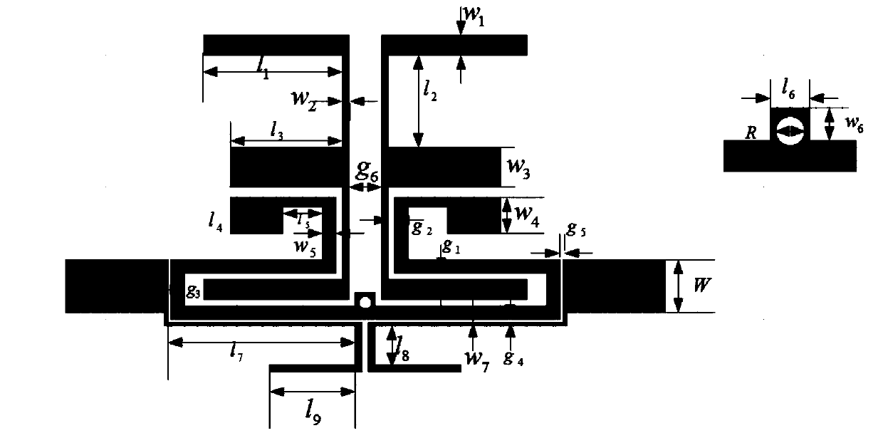
[0034] It can be seen from the figure that it is mainly composed of an E-type dual-pass band filter, a ladder impedance dual-pass band filter and a multi-line feeder on the substrate. Among them, the E-type dual-pass band filter loaded by two open-circuit branches Arranged symmetrically back to back, two multi-line feeders are coupled at one end of the E-type double-pass band filter, and two stepped impedanc...


PUM


Abstract

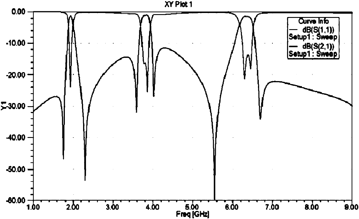
The invention discloses a tri-band bandpass microstrip filter with E-type resonators and stepped impedance resonators. E-type dual-band passband filters loaded to two open circuit branches are arranged in a back-to-back and symmetrical mode on a substrate; two multi-broken line feeder lines are coupled at one ends of the E-type dual-band passband filters; two stepped impedance dual-band passband resonators are embedded between the E-type dual-band passband filters and the multi-broken line feeder lines; and an input port I / P and an output port O / P are arranged at two ends of the two multi-broken line feeder lines. An embedded cross coupling structure with the back-to-back E-type resonators loaded to the open circuit branches and the SIR resonators loaded to short circuit branches is adopted, the passband selectivity is improved, and the size of the filter is reduced. the three-passband microstrip filter for an E-type resonator and a stepped impedance resonator can be applied to RFID, Wimax, and 5GWIFI bands, and has the advantages of simple design, compact structure, convenient processing and debugging, low cost, adjustable passband and good effects.

Description

technical field [0001] The invention relates to a multi-passband microstrip filter, in particular to a three-passband microstrip filter based on an E-shaped resonator and a ladder impedance resonator. Background technique [0002] With the rapid development of multi-band and multi-service communication systems and the advent of the 5G communication era, the demand for filters with multi-band responses is increasing. Therefore, multi-band filters are also one of the hotspots in the field of wireless communication in recent years. . Nowadays, various types of resonators are used to design dual-passband filters, but due to the limitation of the number of frequency bands, they cannot meet the engineering requirements well. [0003] With the development of multimode resonators, the issue of coupling between resonators becomes more important in all passbands, not just between multiple modes of a single resonator, but also between resonators and resonators And the coupling betwee...

Claims


Application Information

Patent Timeline
IPC IPC(8): H01P1/203
CPCH01P1/20381
Inventor 王旭光尤旭颖杨维明彭菊红
Owner YOSHIHIRO COMM EQUIP GRP CO LTD
Learn More