Driving structure based on spherical tire

A technology of spherical tires and driving structures, applied in the direction of wheels, motion deposition, power devices, etc., can solve the problems of high cost, high price, complicated replacement, etc., and achieve the effects of good vibration isolation performance, easy disassembly and maintenance, and simple operation

Pending Publication Date: 2018-02-13
ZHONGBEI UNIV +1
View PDF9 Cites 4 Cited by
  • Summary
  • Abstract
  • Description
  • Claims
  • Application Information

AI Technical Summary

Problems solved by technology

However, there are likely to be the following disadvantages in actual promotion: 1. Electromagnetic field is a technology that is difficult to effectively control. In the absence of tracks, it is relatively difficult to use magnetic levitation technology to control tire rotation; 2. The cost is high. Magnetic levitation technology This is a high-end technology. Using such a technology to realize the movement of the spherical wheel will cost a lot and is difficult to popularize; 3. Using magnetic suspension to control the spherical wheel, the tire manufacturing process is difficult, the replacement is complicated, and the price is expensive

Method used


Image

  • Driving structure based on spherical tire
  • Driving structure based on spherical tire
  • Driving structure based on spherical tire

Examples


Embodiment 1

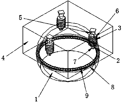
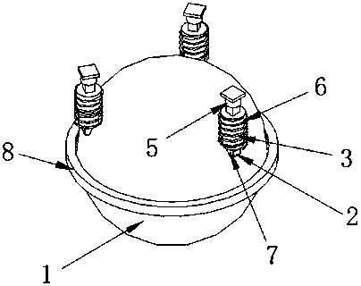
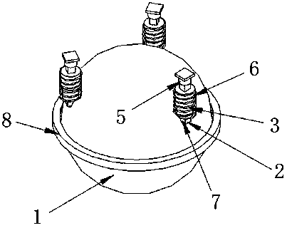
[0028] Such as Figure 1-5 As shown, the present invention provides a kind of driving structure based on spherical tire, comprises spherical tire 1, and the upper half of spherical tire 1 is provided with driving device 111, and driving device 111 comprises driving wheel 2 and driving motor 7, and the top of driving device 111 One end of the hydraulic support shaft 3 is connected, the outside of the hydraulic support shaft 3 is covered with a spring shock absorber 6, the other end of the hydraulic support shaft 3 is connected to the wire mesh shock absorber 5, and one end of the wire mesh shock absorber 5 Fixed on the upper surface of the outer casing 4, between the driving wheel 2 and the spherical tire 1, the friction force is used as the driving force, and the weight of the car body and the human body is fully utilized to increase the driving force (friction force), and evenly distributed three A driving wheel 2 is used to drive the spherical wheel, and the ball bearing 222...

Embodiment 2

[0036] as attached figure 1 As shown, it includes a spherical tire 1 and a driving device 111. The spherical tire 1 adopts an inner hollow structure to reduce the weight of the tire itself. The rubber protective layer outside the spherical tire 1 uses a material with a large friction coefficient, so that the driving wheel 2 and the spherical tire are enlarged. 1 friction, more effective tire control, spherical tire 1 external rubber protective layer, so under the action of gravity, the driving wheel 2 and spherical tire 1 can have a larger contact area, increase friction, more effective tire control .

[0037] Three driving devices 111 are evenly distributed on the outer shell 4 and the spherical tire 1 top, including the driving motor 7 and the driving wheel 2. Under the action of the body and the body's gravity, the driving wheel 2 and the spherical tire 1 outer rubber protection layer can be Large-area contact is realized, frictional force is increased, and the driving of ...


PUM


Abstract

The invention discloses a driving structure based on a spherical tire. The driving structure comprises the spherical tire, driving devices are arranged at the upper half portion of the spherical tireand comprises driving wheels and driving motors, one end part of a hydraulic supporting shaft is connected to the top of each driving device, the outer part of each hydraulic supporting shaft is sleeved with a spring shock absorber, a metal wire mesh oscillating damper is connected to the other end of each hydraulic supporting shaft, and one end of each metal wire mesh oscillating damper is fixedto the upper surface of a shell. When the driving structure based on the spherical tire is in use, the direction and the speed of the three driving wheels can be changed through a control system, so that the speed direction of the driving wheels is in the desired running direction, and the purpose of conducting 360-degree omnibearing motion of the spherical tire is achieved. The spherical wheel driving system has the advantages of being easy to operate, control, dismantle and maintain, and safe and reliable; the whole structure fully considers multiple factors in the vehicle driving process, athree-level damping system is adopted, so that the shock avoidance performance of vehicles in the driving process is better, and the driving structure is safer and more reliable.

Description

technical field [0001] The invention relates to a driving structure of a tire, in particular to a driving structure based on a spherical tire. Background technique [0002] As we all know, spherical tires, a kind of spherical tires, are a conceptual tire first shown by Goodyear at the Geneva Motor Show. Compared with ordinary tires, it can realize 360° movement without dead angle. [0003] At present, people adopt the magnetic levitation technology on how to install and drive spherical tires, and the vehicle can be pushed forward by the magnetic field produced by the coil in the track. However, there are likely to be the following disadvantages in actual promotion: 1. Electromagnetic field is a technology that is difficult to effectively control. In the absence of tracks, it is relatively difficult to use magnetic levitation technology to control tire rotation; 2. The cost is high. Magnetic levitation technology This is a high-end technology, and the cost of using such a te...

Claims


Application Information

Patent Timeline
Patent Type & Authority Applications(China)
IPC IPC(8): B60B19/14B60K7/00
CPCB60B19/14B60K7/0007B60B2900/131
Inventor 杨锋樊文欣李涵
Owner ZHONGBEI UNIV
Why Eureka
Try Eureka