
Permanent magnet direct-driven traction transmission system and method

A technology of traction transmission and permanent magnet direct drive, which is applied in electric traction, motor vehicles, electric vehicles, etc., can solve the problems of increased energy consumption, high electromagnetic noise, and large noise, and achieves reduced transmission loss, reduced electromagnetic radiation, and reduced Effect of motor noise

Inactive Publication Date: 2018-02-16
CRRC NANJING PUZHEN CO LTD
View PDF4 Cites 9 Cited by
  • Summary
  • Abstract
  • Description
  • Claims
  • Application Information

AI Technical Summary

Problems solved by technology

Due to the use of asynchronous permanent magnet direct drive synchronous traction motor, the motor shaft has its own cooling fan, and the noise of the motor is large during operation; the non-direct drive synchronous permanent magnet direct drive synchronous traction motor is water-cooled, and a separate water cooling device needs to be added, which increases the vehicle load. Weight; the traction inverter module adopts high-power IGBT module, its switching frequency is low, the electromagnetic noise is high, and the loss is large; it adopts gearbox transmission, which has certain transmission loss
[0006] The existing traction drive system adopts asynchronous permanent magnet direct drive synchronous traction motor, and the motor shaft has its own cooling fan, which makes the motor run noisy; if non-direct drive permanent magnet synchronous permanent magnet direct drive synchronous traction motor is used, an additional separate water cooling device is required , increase vehicle weight, increase energy consumption
[0007] The traction inverter module adopts high-power IGBT module, which has low switching frequency, high electromagnetic noise and large loss
[0008] The transmission device adopts a gearbox, which has a certain transmission loss

Method used


Image

  • Permanent magnet direct-driven traction transmission system and method
  • Permanent magnet direct-driven traction transmission system and method

Examples


Embodiment Construction

[0035] The present invention will be further explained below in conjunction with the accompanying drawings and specific embodiments. It should be understood that the following specific embodiments are only used to illustrate the present invention but not to limit the scope of the present invention.

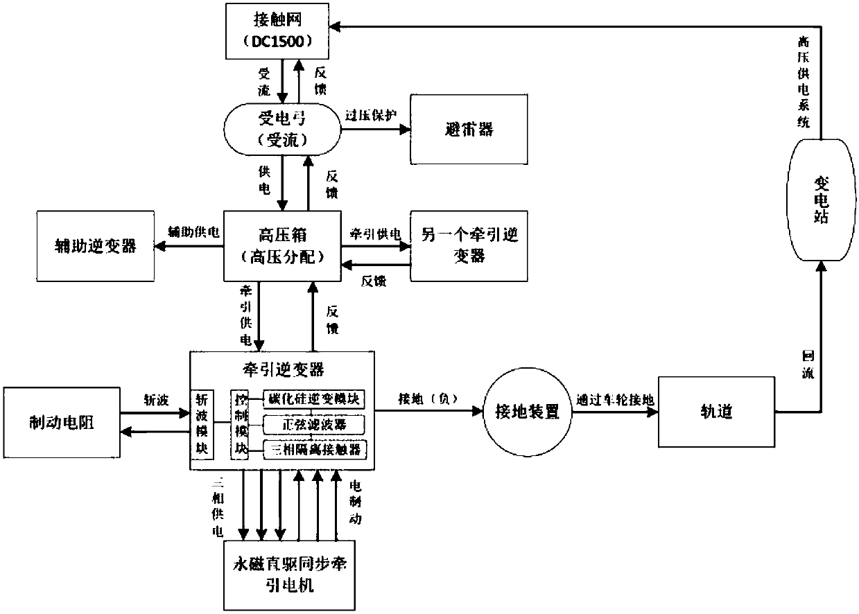
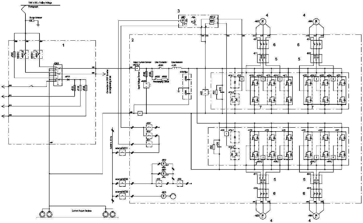
[0036] figure 2 It is a schematic circuit diagram of the present invention, and the names of the marked parts in the figure are: high voltage box 1, traction inverter 2, braking resistor 3, permanent magnet direct drive synchronous traction motor 4, sinusoidal filter 5, three-phase isolation contactor 6 , silicon carbide inverter module 7, figure 1 It is a connection block diagram of the present invention. It can be seen from the accompanying drawings that the permanent magnet direct drive traction transmission system is used to drive the motor car in the train, and the traction transmission system can drive two motor cars at the same time.

[0037] The traction drive system in...


PUM


Abstract

The invention discloses a permanent magnet direct-driven traction transmission system and method. The permanent magnet direct-driven traction transmission system comprises a high-voltage box, tractioninverters, a permanent magnet direct-driven synchronous traction motor and a silicon carbide inversion module; the high-voltage box is connected with the traction inverters; and the traction inverters are in drive connection with the permanent magnet direct-driven synchronous traction motor. The permanent magnet direct-driven traction transmission method comprises the steps that 1, the high-voltage box is supplied with high-voltage electricity; 2, the high-voltage box distributes the high-voltage electricity to the traction inverters; 3, the traction inverters output the three-phase alternating current through the silicon carbide inversion module to an input power source inverter; 4, the three-phase alternating current is filtered into standard sine waves through a sine filter; and 5, thesine waves pass through a three-phase isolation contactor to be output to the permanent magnet direct-driven synchronous traction motor, and the permanent magnet direct-driven synchronous traction motor drives a train to advance. Electricity supply is more efficient, and electromagnetic radiation of cables between the permanent magnet direct-driven synchronous traction motor and the inverters isreduced significantly.

Description

technical field [0001] The invention relates to a permanent magnet direct-drive traction transmission system and a method, and belongs to the technical field of rail transit vehicle traction transmission systems. Background technique [0002] The traction drive system is one of the most critical subsystems in the rail transit system. The traction drive system provides traction force and electric braking force for rail transit vehicles, and the traction drive system has a lot of equipment. Therefore, the design of the traction drive system for light weight, energy saving and noise reduction is very important for the normal operation of the vehicle. [0003] The traction drive system provides driving power for the permanent magnet direct drive synchronous traction motor through the traction inverter. The permanent magnet direct drive synchronous traction motor is installed on the vehicle bogie, drives the axle transmission through the transmission gear box, and drives the trai...

Claims


Application Information

Patent Timeline
IPC IPC(8): B60L9/00
CPCB60L9/00B60L2200/26B60L2220/14Y02T10/72
Inventor 张爱平梁汝军章义李军杨凡张潜葛莲
Owner CRRC NANJING PUZHEN CO LTD
Learn More