Three-level full-bridge soft switch current conversion circuit and control method therefor

A technology of full-bridge inverter circuit and control method, which is applied in the direction of adjusting electric variables, control/regulation systems, high-efficiency power electronic conversion, etc., and can solve problems such as reducing circuit reliability, individually controllable switching tubes, and increasing circuit complexity. , to achieve the effect of dynamic voltage clamping, simple and effective control method, and simplified design complexity

Pending Publication Date: 2018-02-16
AOTAI ELECTRIC
View PDF5 Cites 10 Cited by
  • Summary
  • Abstract
  • Description
  • Claims
  • Application Information

AI Technical Summary

Problems solved by technology

[0003] Chinese patent 01127182 "Zero-voltage and zero-current switching hybrid full-bridge three-level DC converter", although it belongs to a three-level inverter circuit, half of it is a two-level bridge arm, so it also has a two-level converter circuit shortcoming
[0005] When only parasitic capacitance is used, the soft switching effect is poor due to the small capacitance
When a large capacitor is connected in parallel at both ends of the switch tube, under no-load or light-load conditions, the parallel capacitor will be discharged directly through the switch tube, which will affect the reliability of the device, and the parallel capacitor of the switch tube will reduce the controllability of the circuit. characteristics, especially at low power output
In addition, due to the need to achieve midpoint potential balance, the control logic of the inverter circuit is relatively complex, which significantly increases the number and cost of the control circuit components, and the increase in the number of components will reduce the reliability of the circuit
The dynamic voltage clamping of the switching tube is a problem that must be solved in every three-level DC-AC-DC converter circuit. Adding flying capacitors at both ends of the clamping diode can achieve the effect of dynamic voltage clamping of the switching tube, but it will increase circuit complexity
Using a specific control method, the dynamic voltage clamping of the switching tube can also be realized, but it is usually accompanied by complex control, the switching tube needs to be individually controllable, and the design of the driving circuit is complicated.

Method used


Image

  • Three-level full-bridge soft switch current conversion circuit and control method therefor
  • Three-level full-bridge soft switch current conversion circuit and control method therefor
  • Three-level full-bridge soft switch current conversion circuit and control method therefor

Examples


Embodiment 1

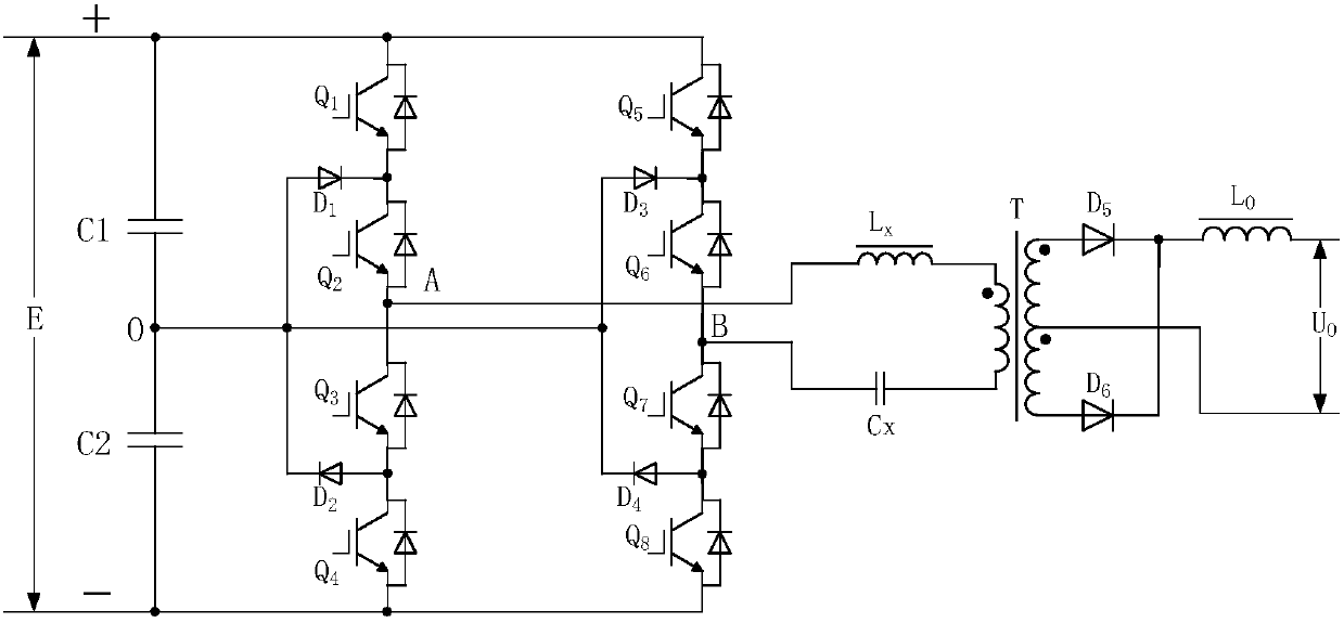
[0048] The invention discloses a three-level full-bridge soft-switching converter circuit, such as figure 1As shown, including: input voltage dividing capacitor, inverter circuit, saturated inductor, DC blocking capacitor, transformer and output circuit. The input voltage dividing capacitor is formed by connecting two capacitors C1 and C2 in series. The inverter circuit is composed of two three-level half-bridge arms, the switch tubes Q1~Q4 are connected in series in sequence, form a bridge arm with the clamping diodes D1, D2, the switch tubes Q5~Q8 are connected in series, and the clamping diodes D3, D4 Form another bridge arm. The connection points of the switch tubes Q1 and Q2 are connected to the cathode of the clamping diode D1, the connection points of the switch tubes Q3 and Q4 are connected to the anode of the clamping diode D2, the anode of the clamping diode D1 is connected to the cathode of D2, and the connection point is connected to the The midpoints of the volt...

Embodiment 2

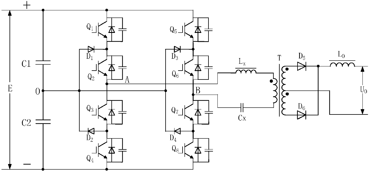
[0053] Such as figure 2 As shown, on the basis of the three-level full-bridge soft-switching converter circuit in Embodiment 1, capacitors are connected in parallel at both ends of each switching tube of the three-level bridge arm. However, after the capacitors are connected in parallel, an additional circuit needs to be added to ensure that the parallel capacitors will not be directly discharged through the switch tube under no-load or light-load conditions. Or it is applied in occasions where there is basically no no-load or light-load state, which limits the application environment of the converter circuit.

[0054] Other structures and working principles of the three-level full-bridge soft-switching converter circuit are the same as those in Embodiment 1, and will not be repeated here.

Embodiment 3

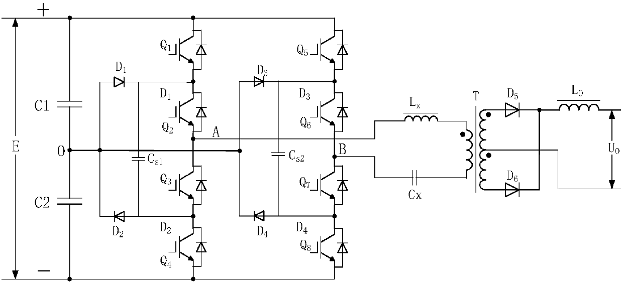
[0056] Such as image 3 As shown, on the basis of the three-level full-bridge soft-switching converter circuit of the first embodiment, after the clamping diodes D1 and D2 are connected in series, and after the diodes D3 and D4 are connected in series, the flying capacitors are connected in parallel at both ends thereof.

[0057] Other structures and working principles of the three-level full-bridge soft-switching converter circuit are the same as those in Embodiment 1, and will not be repeated here.


PUM


Abstract

The invention discloses a three-level full-bridge soft switch current conversion circuit and a control method therefor, and the circuit comprises an input capacitor C1, an input capacitor C2, a three-level full-bridge inversion circuit, a transformer, and an output circuit. A connection line between the three-level full-bridge inversion circuit and the primary side of the transformer is in seriesconnection with a saturation inductor and a blocking capacitor. The invention proposes a control method for the circuit, and the method is simple and effective. The method can cooperate with a currentconversion circuit to achieve a soft switch effect, also can simplify the design complexity of the drive circuit, just needs two pulse transformers and a matched drive circuit, and can achieve the drive isolation and drive power transmission of eight switching tubes without an additional isolation power supply.

Description

technical field [0001] The invention relates to the field of DC-AC-DC converter circuits, in particular to a three-level full-bridge soft-switch converter circuit and a control method thereof. Background technique [0002] The traditional two-level converter circuit has the advantages of simple topology and easy control, and is widely used in various DC-AC-DC converter circuits. However, the two-level converter circuit also has problems such as high requirements for the withstand voltage of the switching tube, large switching stress, and difficulty in increasing the frequency, which are greatly restricted in high-voltage input applications. The three-level inverter circuit has half the withstand voltage of the switch tube as the two-level inverter circuit, the switch stress is small, and it is easier to achieve high frequency. In the case of high voltage input, the application advantage is obvious. [0003] Chinese patent 01127182 "Zero-voltage and zero-current switching hy...

Claims


Application Information

Patent Timeline
Patent Type & Authority Applications(China)
IPC IPC(8): H02M3/335H02M7/5387H02M7/5395H02M7/487
CPCH02M3/33569H02M7/487H02M7/53871H02M7/5395H02M1/0058Y02B70/10
Inventor 张光先李昊边乐民张甫国刘月
Owner AOTAI ELECTRIC
Why Eureka
Try Eureka