
Ultra-high pressure anti-slipping mold for discharging plasma sintering

A discharge plasma and ultra-high voltage technology, applied in the field of ultra-high pressure anti-slip molds, can solve the problems of reducing the service life of the mold, increasing the cost of sample preparation, and dropping the sample, so as to improve production efficiency, shorten loading and unloading time, and withstand The effect of pressure increase

Active Publication Date: 2018-02-23
NORTHWESTERN POLYTECHNICAL UNIV
View PDF8 Cites 17 Cited by
  • Summary
  • Abstract
  • Description
  • Claims
  • Application Information

AI Technical Summary

Problems solved by technology

Although this mold can increase the pressure during sintering to a certain extent, since the indenter is still made of graphite, the pressure that can be increased is limited.
And if it is used for a long time, the gap between the inner and outer molds of the mold will gradually increase. During the sintering process, the inner and outer molds may slide relative to each other, which will cause the problem of the sample falling, which greatly reduces the service life of the mold and increases cost of sample preparation

Method used


Image

  • Ultra-high pressure anti-slipping mold for discharging plasma sintering
  • Ultra-high pressure anti-slipping mold for discharging plasma sintering

Examples


Embodiment Construction

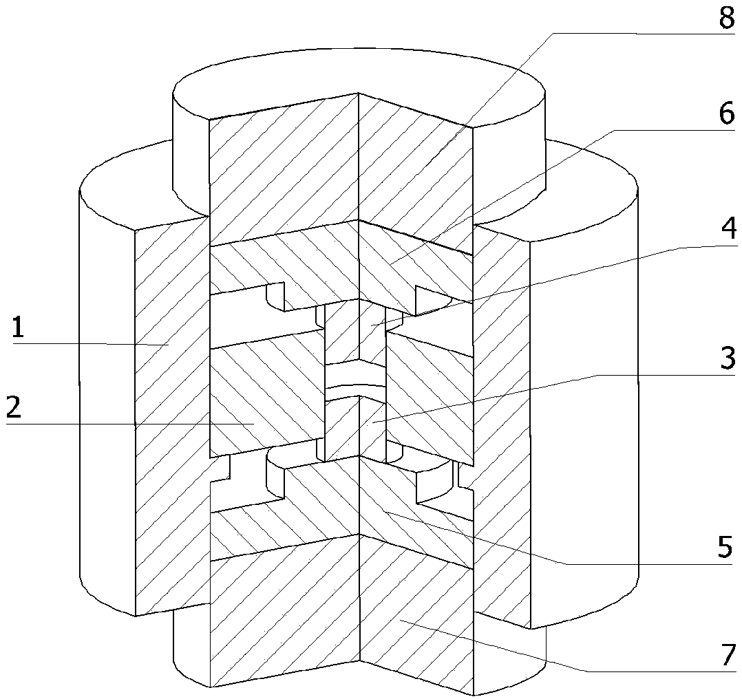
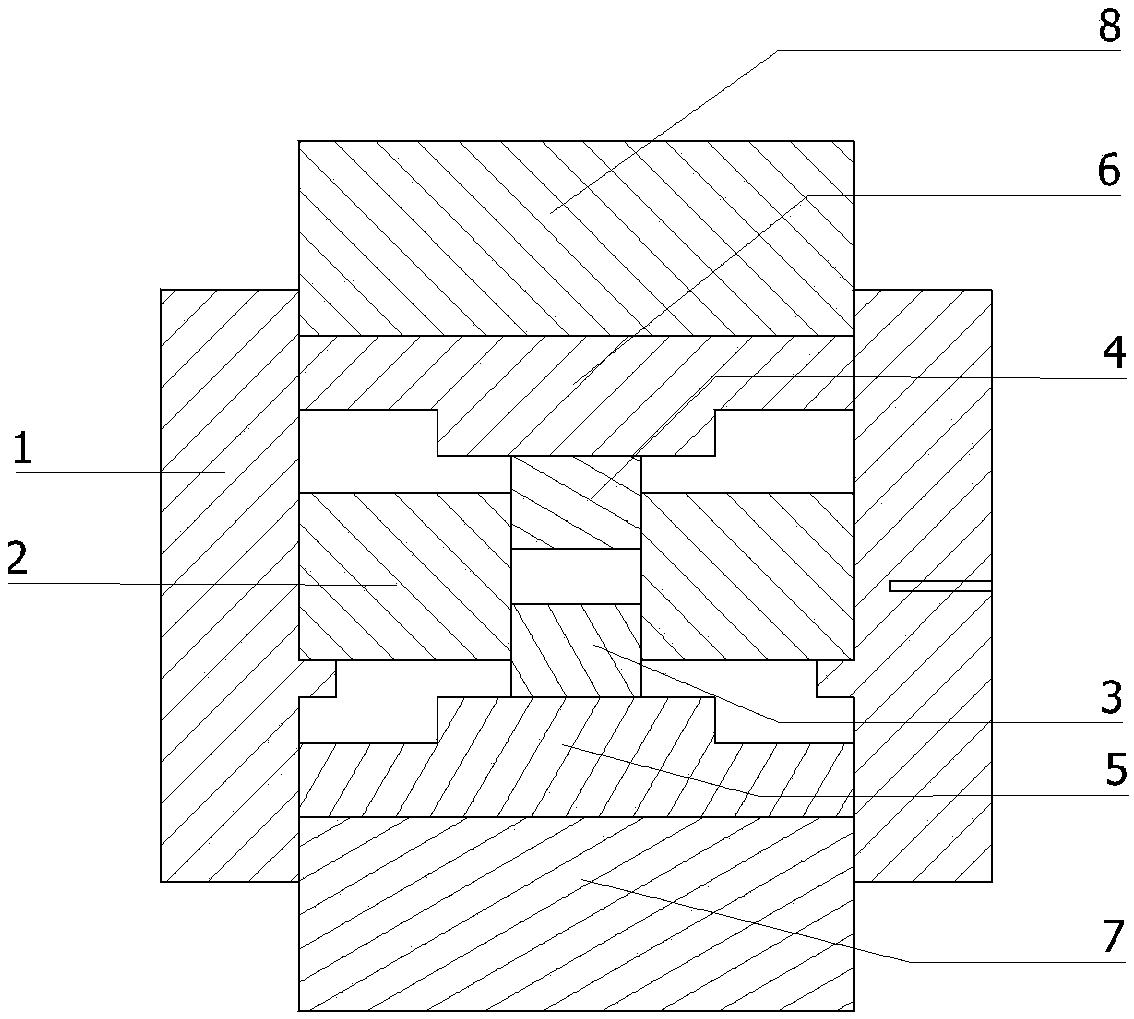
[0020] This embodiment is an ultra-high pressure anti-slip mold for spark plasma sintering; first place the nanocrystalline powder prepared in advance in the sintering area formed by the inner mold, the upper inner pressure head and the lower inner pressure head to ensure that the powder Tight packing in the sintering zone. When working, the mold is placed in the discharge plasma sintering equipment, and the power is turned on to make the whole mold heated up evenly, and at the same time, the pressure acts on the outer pressure head. The block is pushed to move to the inside of the mold, the force is transmitted through the steps, and finally the pressure is applied to the powder sample, so that the powder sample is sintered under pressure. Due to the limited pressure provided by the spark plasma sintering equipment, the pressure acting on the sample is greatly increased through the high-strength tungsten carbide step force transmission, which can effectively improve the densi...


PUM


Abstract

The invention discloses an ultra-high pressure anti-slipping mold for discharging plasma sintering. The ultra-high pressure anti-slipping mold is formed by combining parts formed and processed from high-purity graphite and parts formed and processed from a high-strength tungsten carbide alloy; an inner mold is embedded in the upper portion of a boss of the side wall of an outer mold, and the outermold wall is provided with a radial blind hole which is used for mounting of a thermocouple to monitor the temperature in real time. An upper inner pressure head and a lower inner pressure head are correspondingly embedded in the upper part and the lower part of the inner side wall of the inner mold, and a cavity formed between the upper inner pressure head as well as the lower inner pressure head and the inner mold is a sintering zone which is used for filling powder of a sintering testing piece. One ends of an upper cushion block and a lower cushion block are planes and abut against a lowerouter pressure head and an upper outer pressure head, and the other end faces of the upper cushion block and the lower cushion block are provided with disc-shaped bulges, and the disc-shaped bulges and the lower inner pressure head and the upper inner pressure head are symmetrically mounted in a fit mode. Under the premise that smooth electricity conducting is ensured, the mold can effectively improve the sintering pressure applied on a sample, and prevent relative slipping of the inner mold and the outer mold in the sintering process after the mold is used for a long time; and thus the production cost is reduced, and the production efficiency is improved.

Description

technical field [0001] The invention relates to the technical field of powder metallurgy sintering equipment, in particular to an ultra-high pressure anti-slip mold for spark plasma sintering. Background technique [0002] In recent years, nanocrystalline materials have aroused a research boom at home and abroad because of their excellent properties. However, due to limited preparation techniques, it is currently difficult to prepare large nanocrystalline bulk materials. In contrast, the technology of preparing nanocrystalline powder by high-energy ball milling is relatively mature, so the preparation of powder into bulk nanocrystalline materials by powder metallurgy has become a current research hotspot. At present, nanocrystalline bulk materials are mainly prepared by hot isostatic pressing (HIP), ultra-high pressure sintering (UPS) and spark plasma sintering (SPS). [0003] The spark plasma sintering method is to put metal powder into a mold made of graphite and other ma...

Claims


Application Information

Patent Timeline
Patent Type & Authority Applications(China)
IPC IPC(8): B22F3/105B22F3/03
CPCB22F3/03B22F3/105B22F2202/13
Inventor 陈豫增单贵斌宫明明董浩张文祥刘峰
Owner NORTHWESTERN POLYTECHNICAL UNIV
Learn More