Ceramsite manufacturing system

A technology of ceramsite and microwave suppression, which is applied to ceramic products, manufacturing tools, clay products, etc., can solve the problems of high energy consumption, and achieve the effect of simple structure, high reliability and strong operability

Inactive Publication Date: 2018-02-23
CHNA ENERGY INVESTMENT CORP LTD +2
View PDF9 Cites 2 Cited by
  • Summary
  • Abstract
  • Description
  • Claims
  • Application Information

AI Technical Summary

Problems solved by technology

[0007] The main purpose of this application is to provide a production system of ceramsite to sol

Method used


Image

  • Ceramsite manufacturing system

Examples


Embodiment

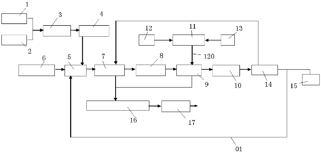
[0050] Such as figure 1 As shown, the ceramsite production system includes fly ash storage equipment 1, water storage equipment 2, ball forming equipment 3, material distribution equipment 4, conveying components, propulsion equipment 6, preheating equipment 7, microwave heating device, electric control equipment 12. Water cooling equipment 13, cooler 14, crushing and screening equipment 15, denitrification, desulfurization and dust removal device 16, induced draft fan 17 and hollow device. Among them, the conveying components include kiln car and running track, wherein the running track includes loading track and unloading track, microwave heating device includes feeding microwave suppressor 8, microwave sintering furnace 9, discharging microwave suppressor 10, microwave energy feeding equipment 11 and microwave guide 120. The specific connection relationship is as figure 1 shown.

[0051] The working process of the production system includes:

[0052] The coarse ash in t...


PUM


Abstract

The invention provides a ceramsite manufacturing system. The manufacturing system comprises balling equipment, a conveying assembly and a microwave heating device, wherein the balling equipment communicates with coal ash storage equipment and is used for utilizing the coal ash, a bonding agent and water for preparing wet balls. The conveying assembly is used for conveying the wet balls output by the balling equipment. The conveying assembly conveys the wet balls into the microwave heating device, and the microwave heating device is used for sintering the wet balls into ceramsite. The efficiency of manufacturing the ceramsite through the manufacturing system is high, and energy consumption is low.

Description

technical field [0001] This application relates to the production field of ceramsite, in particular, to a production system of ceramsite. Background technique [0002] Fly ash is a fine particle produced during the combustion of coal in the boiler of a thermal power plant. It is a powdery solid mixture formed after the flue gas is discharged from the furnace. It is a kind of industrial waste. It mainly includes SiO 2 、Al 2 o 3 , CaO, Fe 2 o 3 , carbon and other metal and non-metal oxides. [0003] At present, my country's electricity production is still dominated by coal-fired power generation, and the operation of coal-fired power plants will produce a large amount of fly ash. According to statistics, by the end of 2015, my country's installed capacity of thermal power reached 1.02 billion kilowatts, and the annual discharge of fly ash was about 600 million tons. ) are likely to cause pollution of surface water, groundwater and atmospheric environment, endanger human ...

Claims


Application Information

Patent Timeline
IPC IPC(8): B28B15/00B28B1/00B28B11/24C04B33/135C04B33/32C04B38/00
CPCB28B1/004B28B11/241B28B15/00C04B33/1352C04B33/32C04B38/009C04B2235/667Y02P40/60
Inventor 陈磊张永桂
Owner CHNA ENERGY INVESTMENT CORP LTD
Why Eureka
Try Eureka