Preparation of ultra-low loss optical fiber preform rod and optical fibers by axial vapor deposition method

An optical fiber and ultra-low technology, which is applied in the field of axial vapor deposition to prepare ultra-low loss optical fiber preforms and optical fibers, and can solve problems such as poor uniformity of radial refractive index, difficult deep fluorine doping process, and difficulty in mass production. , to achieve the effect of prolonging the production cycle, uncomplicated production process and small air flow

Inactive Publication Date: 2018-02-23
HENGTONG OPTICAL MATERIAL CO LTD +1
View PDF7 Cites 20 Cited by
  • Summary
  • Abstract
  • Description
  • Claims
  • Application Information

AI Technical Summary

Problems solved by technology

Chinese patents CN103472529A and CN102654602A both provide a pure silicon core solution to prepare low-loss optical fibers. The core layer is not doped with Ge, the inner cladding is deeply doped with fluorine, and the outer cladding is normally doped with fluorine. Both involve the preparation of a deep fluorine-doped inner cladding. The process is difficult, the uniformity of the radial refractive index is poor, the process is prepared by the in-tube method, and the size of the optical rod is limited by the basic quartz tube, so it is difficult to achieve mass production
However, the production speed of this method is slow, so the efficiency is low and the cost is high after industrialization

Method used


Image

  • Preparation of ultra-low loss optical fiber preform rod and optical fibers by axial vapor deposition method
  • Preparation of ultra-low loss optical fiber preform rod and optical fibers by axial vapor deposition method
  • Preparation of ultra-low loss optical fiber preform rod and optical fibers by axial vapor deposition method

Examples


Embodiment 1

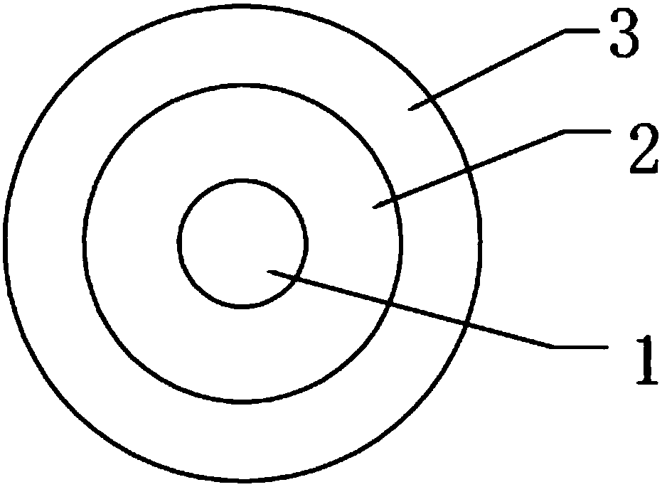
[0031] Such as figure 1 As shown, an ultra-low loss optical fiber of this embodiment includes a core layer 1, an inner cladding layer 2 and an outer cladding layer 3 coated in sequence, the core layer 1 is a pure silicon rod doped with alkali metal ions, and the core layer 1 is doped with The concentration of impurity alkali metal ions is 200ppm, the inner cladding 2 is a fluorine-doped quartz sleeve, and the outer cladding 3 is an OVD synthetic outer cladding; the relative refractive index difference between the core 1 and the inner cladding 2 is Δ1≈0.4%, and the inner cladding 2 and the outer cladding Layer 3 has a relative refractive index difference Δ2≈-0.3%.

[0032] The inner wall of the fluorine-doped quartz sleeve is deposited by gas phase reaction to form a fluorine-doped quartz layer layer by layer until the refractive index matches the relative refractive index difference between the core layer 1 and the inner cladding layer 2 .

[0033] The doping concentration of...

Embodiment 2

[0050] Such as figure 1 As shown, an ultra-low loss optical fiber of this embodiment includes a core layer 1, an inner cladding layer 2 and an outer cladding layer 3 coated in sequence, the core layer 1 is a pure silicon rod doped with alkali metal ions, and the core layer 1 is doped with The concentration of impurity alkali metal ions is 500ppm, the inner cladding 2 is a fluorine-doped quartz sleeve, and the outer cladding 3 is an OVD synthetic outer cladding; the relative refractive index difference between the core 1 and the inner cladding 2 is Δ1≈0.6%, and the inner cladding 2 and the outer cladding Layer 3 has a relative refractive index difference Δ2≈-0.4%.

[0051] The inner wall of the fluorine-doped quartz sleeve is deposited by gas phase reaction to form a fluorine-doped quartz layer layer by layer until the refractive index matches the relative refractive index difference between the core layer 1 and the inner cladding layer 2 .

[0052] The doping concentration of...

Embodiment 3

[0056] Such as figure 1 As shown, an ultra-low loss optical fiber of this embodiment includes a core layer 1, an inner cladding layer 2 and an outer cladding layer 3 coated in sequence, the core layer 1 is a pure silicon rod doped with alkali metal ions, and the core layer 1 is doped with The concentration of impurity alkali metal ions is 400ppm, the inner cladding 2 is a fluorine-doped quartz sleeve, and the outer cladding 3 is an OVD synthetic outer cladding; the relative refractive index difference between the core 1 and the inner cladding 2 is Δ1≈0.5%, and the inner cladding 2 and the outer cladding Layer 3 has a relative refractive index difference Δ2≈-0.4%.

[0057] The inner wall of the fluorine-doped quartz sleeve is deposited by gas phase reaction to form a fluorine-doped quartz layer layer by layer until the refractive index matches the relative refractive index difference between the core layer 1 and the inner cladding layer 2 .

[0058] The doping concentration of...


PUM

PropertyMeasurementUnit
diameteraaaaaaaaaa
diameteraaaaaaaaaa

Abstract

The invention discloses ultra-low loss optical fibers. Alkali metal elements are added during the VAD deposition technological process to reduce the viscosity of a core layer, enable the core layer tobe more matched with an inner cladding layer and an outer cladding layer, and reduce the internal stress, so that the ultra-low loss fibers with low transmission attenuation can be manufactured. A preparation method of the ultra-low loss optical fibers, disclosed by the invention, is based on the traditional VAD deposition process. A small amount of alkali metal is doped in the deposition process, and the doping amount is small and the gas flow rate is small, so that the normal deposition process is not affected too much, and doping is finished while depositing, and therefore, the productioncycle is prolonged, and then the production stability can be ensured, the production process is not complex, and the preparation method can be used in large-scale production. By the adoption of the invention, optical fiber attenuation can be optimized to ultra-low loss standards, and relay stations can be reduced in high speed transmission with long distance and low attenuation to lower the cost and improve the transmission quality.

Description

technical field [0001] The invention relates to the technical field of optical fiber communication, in particular to an axial vapor deposition method for preparing ultra-low loss optical fiber preform rods and optical fibers. Background technique [0002] With the continuous development of long-distance optical fiber transmission, especially the rapid development of Internet technology and 4G and passive optical network technologies, the requirements for reducing optical fiber loss are getting higher and higher. The current ultra-low loss optical fiber core rods mostly use pure silicon core rods containing trace amounts of alkali metals. Chinese patents CN103472529A and CN102654602A both provide a pure silicon core solution to prepare low-loss optical fibers. The core layer is not doped with Ge, the inner cladding is deeply doped with fluorine, and the outer cladding is normally doped with fluorine. Both involve the preparation of a deep fluorine-doped inner cladding. The p...

Claims


Application Information

Patent Timeline
Patent Type & Authority Applications(China)
IPC IPC(8): C03B37/018C03B37/027G02B6/02G02B6/036
CPCC03B37/01853C03B37/027C03B2203/32G02B6/02004G02B6/03622C03B37/02
Inventor 朱亦奇劳雪刚王友兵和联科
Owner HENGTONG OPTICAL MATERIAL CO LTD
Why Eureka
Try Eureka