Low-temperature waste heat treatment method for dry tail gas

A technology of low-temperature waste heat and treatment methods, which is applied in the directions of dry gas arrangement, separation methods, chemical instruments and methods, etc., to achieve the effect of heat energy upgrading and conversion, and process optimization

Inactive Publication Date: 2018-02-23
苏州卓润赛豚节能环保科技有限公司
View PDF7 Cites 3 Cited by
  • Summary
  • Abstract
  • Description
  • Claims
  • Application Information

AI Technical Summary

Problems solved by technology

[0009] The purpose of the present invention is to provide a low-temperature waste heat treatment method for dry tail gas, so as to solve one or more technical defects in the prior art, and achieve the purpose of fully recycling low-temperature waste heat and energy saving and environmental protection

Method used


Image

  • Low-temperature waste heat treatment method for dry tail gas
  • Low-temperature waste heat treatment method for dry tail gas
  • Low-temperature waste heat treatment method for dry tail gas

Examples


Embodiment

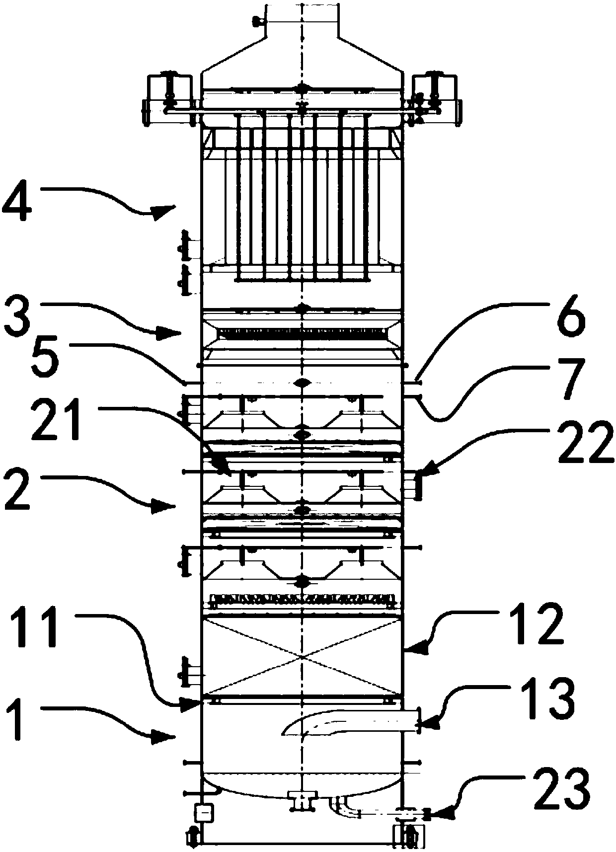
[0035] Embodiment: A low-temperature waste heat treatment equipment for drying tail gas, including a tail gas treatment chamber, the tail gas treatment chamber is sequentially provided with a vacuum flash section 1, a spray heat collection section 2, an atomization dust removal section 3, Electrostatic precipitator section 4.

[0036] In this embodiment, the spray heat collecting section 2 includes at least one layer of spray washing mechanism, the tail gas passes through the spray washing mechanism from bottom to top, and the spray washing mechanism sprays and washes the tail gas , heat is enriched through the circulating water.

[0037] In this embodiment, the spray washing mechanism in the spray heat collecting section 2 has three layers, and each layer of the spray washing mechanism includes a plurality of nozzles 21 , a liquid inlet 22 and a liquid outlet 23 . Wherein, the nozzle 21 is arranged on the cavity wall of the exhaust gas treatment chamber and is arranged aroun...


PUM


Abstract

The invention discloses a low-temperature waste heat treatment method for dry tail gas. The low-temperature waste heat treatment method comprises the following steps that S1, tail gas passes through drying equipment to go into a spraying heat collection section; S2, circulating water is sprayed to dissolve particulate matter and acid gas in the tail gas and goes into a vacuum flashing section, andthe treated tail gas goes into an atomization dust removal section; S3, waste heat of the circulating water is collected through the vacuum flashing section, and the circulating water is returned tothe spraying heat collection section; S4, part of the circulating water is atomized to form mist to make the particulate matter in the tail gas going into the atomization dust removal section gather and settle, and the treated tail gas goes into an electrostatic dust collection section; and S5, the tail gas is subjected to electrostatic dust collection treatment, and the remaining tail gas is cyclically introduced to the spraying heat collection section.

Description

technical field [0001] The invention relates to the fields of tail gas treatment and the like, in particular to a low-temperature waste heat treatment method for drying tail gas. Background technique [0002] Material drying is one of the important production processes of chemical enterprises. Its purpose is to remove the moisture in some raw materials, semi-finished products and finished products, so that the materials are convenient for packaging, transportation, storage, processing and use. The drying process involves many fields such as chemical industry, petrochemical, pharmaceutical, food, papermaking, wood, food and agricultural by-product processing, building materials, and environmental protection. Since drying is to vaporize and remove the moisture in the material by means of heating, drying is one of the unit operations with high energy consumption. According to statistics, the sum of drying energy consumption in various industries in the UK accounts for about 8%...

Claims


Application Information

Patent Timeline
Patent Type & Authority Applications(China)
IPC IPC(8): F26B21/00F25B30/00B01D53/14B01D50/00
CPCF26B21/002B01D50/00B01D53/1456F25B30/00
Inventor 王莉华姜瑞雨刘方成吴建荣申涛
Owner 苏州卓润赛豚节能环保科技有限公司
Why Eureka
Try Eureka