
3D NAND flash memory channel hole preparing method and 3D NAND flash memory

A manufacturing method and channel technology, applied in semiconductor/solid-state device manufacturing, electrical components, electrical solid-state devices, etc., can solve the problems of product formation impact, disconnection at the bottom of polysilicon, high cost, etc., and achieve easy and stable control and uniformity of molding Good, damage prevention effect

Active Publication Date: 2018-02-23
YANGTZE MEMORY TECH CO LTD
View PDF4 Cites 19 Cited by
  • Summary
  • Abstract
  • Description
  • Claims
  • Application Information

AI Technical Summary

Problems solved by technology

[0009] 1) However, in the above method, there are following defects: in the polysilicon wet etching back process in the S2 step, it is difficult to control the uniformity of the polysilicon thickness, such as figure 2 As shown in the photo, the thickness of the polysilicon around the channel hole is 6.66 (nm), 6.84 (nm), 7.02 (nm) and 7.2 (nm) in the four directions of the circumference, the difference is about 8%, and the polysilicon Susceptible to damage, thereby affecting product formation
The barrier oxide layer prepared by the atomic layer deposition method (ALD) used in the S3 step is not dense enough, due to the problems of the process itself, particles and pores are generated in the deposited layer, and the cost is high, and the deposition efficiency is low; it is easy to integrate in the subsequent process Bottom disconnection issues forming polysilicon, such as Figure 3a and 3b As shown, it can be seen that the bottom of the polysilicon layer 1-6 deposited in the second layer is not connected. It can also be seen from the figure that the thickness of the polysilicon deposited in the second layer is inconsistent at different positions. The thickness deposited in the silicon epitaxial layer is the largest, and in the ONO The thickness of the structural part deposited is the smallest (T Si > T a-Si > T ONO )

Method used

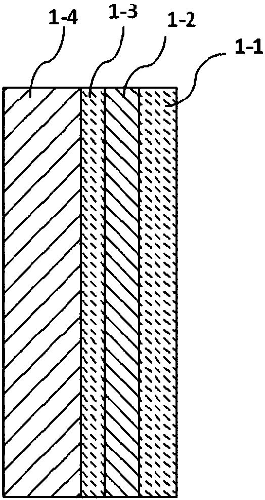
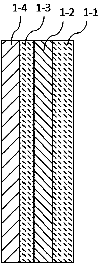
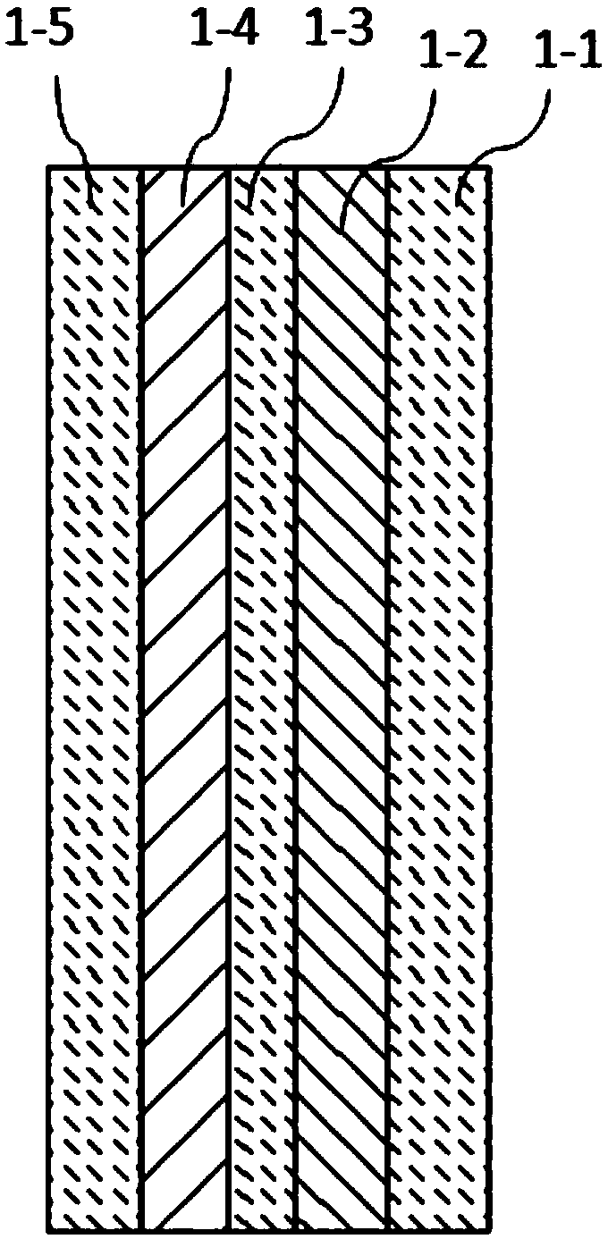

Image

  • 3D NAND flash memory channel hole preparing method and 3D NAND flash memory
  • 3D NAND flash memory channel hole preparing method and 3D NAND flash memory
  • 3D NAND flash memory channel hole preparing method and 3D NAND flash memory

Examples


Embodiment Construction

[0042] Exemplary embodiments of the present disclosure will be described in more detail below with reference to the accompanying drawings. Although exemplary embodiments of the present disclosure are shown in the drawings, it should be understood that the present disclosure may be embodied in various forms and should not be limited by the embodiments set forth herein. Rather, these embodiments are provided for more thorough understanding of the present disclosure and to fully convey the scope of the present disclosure to those skilled in the art.

[0043] In the interest of clarity, not all features of an actual implementation are described. In the following description, well-known functions and constructions are not described in detail since they would obscure the invention with unnecessary detail. It should be appreciated that in the development of any actual embodiment, numerous implementation details must be worked out to achieve the developer's specific goals, such as ch...


PUM


Abstract

The invention provides a 3D NAND flash memory channel hole preparing method and 3D NAND flash memory. The method comprises the steps of conducting deposition in a channel hole of a substrate stackingstructure, and respectively forming a blocking layer, an accumulating layer, and a tunneling layer; conducting deposition of a first polysilicon layer; conducting low-temperature free radical oxidation on the polysilicon layer of the first deposition, and forming a masking oxide layer; conducting etching on the masking oxide layer, the first polysilicon layer, the tunneling layer, the accumulatinglayer and the blocking layer at the bottom part of the channel hole until a silicon epilayer is exposed and over etching is conducted on the silicon epilayer at a certain depth; Removing the maskingoxide layer and conducting pre-cleaning before the deposition of a second polysilicon layer; conducting deposition on the second polysilicon layer. The invention is advantageous in that as the low-temperature free radical oxidation technology is adopted to form the masking oxide layer and diluted hydrofluoric acid is adopted to conduct the pre-cleaning of the second polysilicon layer before deposition, the step of etchback of the polysilicon can be saved, and the channel hole polysilicon layer with good uniformity and high quality can be formed, and cost is low and reliability is high.

Description

technical field [0001] The invention relates to the field of semiconductor manufacturing, in particular to a method for preparing 3D NAND flash memory channel hole polysilicon. Background technique [0002] In order to improve the density of memory devices, the industry has made extensive efforts to develop methods of reducing the size of two-dimensionally arranged memory cells. As the size of memory cells in two-dimensional (2D) memory devices continues to shrink, signal collisions and interference can increase significantly, making it difficult to perform multi-level cell (MLC) operations. In order to overcome the limitations of 2D memory devices, research on memory devices with a three-dimensional (3D) structure has gradually heated up this year, and integration density is increased by three-dimensionally arranging memory cells on a substrate. [0003] In the production of 3D NAND flash memory, it involves the preparation method of each functional layer of the channel ho...

Claims


Application Information

Patent Timeline
Patent Type & Authority Applications(China)
IPC IPC(8): H01L27/11573H01L27/11578H01L27/1157H01L21/768H10B43/40H10B43/20H10B43/35
CPCH01L21/76877H10B43/20H10B43/40H10B43/35
Inventor 唐兆云隋翔宇陆智勇赵新梅
Owner YANGTZE MEMORY TECH CO LTD
Learn More