Laser cutting machine

A technology of laser cutting machine and laser cutting head, which is applied in the direction of laser welding equipment, welding equipment, metal processing equipment, etc., and can solve the problems that special processes cannot be realized, cannot be processed, and the cost of molds is high.

Pending Publication Date: 2018-03-02
GUANGDONG ZHENGYE TECH
View PDF11 Cites 6 Cited by
  • Summary
  • Abstract
  • Description
  • Claims
  • Application Information

AI Technical Summary

Problems solved by technology

[0004] Although the production efficiency of the punching machine is higher than that of the gong machine when stamping the aluminum substrate, the cost of the mold is high, and different substrates need to be replaced with different molds, the processing cost is high, and the processing accuracy is also low. Generally, the dimensional accuracy of the processed substrate is ±0.1mm. Precision aluminum substrates with high requirements cannot be processed; in addition, some substrates cannot be stamped, such as IC parts and circuits on the substrate, stamping will affect the IC parts and circuits on the substrate, and some special processes cannot be realized Processing holes with a diameter of ≤0.3mm, slits with a slit width of ≤0.3mm, etc.

Method used


Image

  • Laser cutting machine
  • Laser cutting machine
  • Laser cutting machine

Examples


Embodiment Construction

[0039] The following will clearly and completely describe the technical solutions in the embodiments of the present invention with reference to the accompanying drawings in the embodiments of the present invention. Obviously, the described embodiments are only some, not all, embodiments of the present invention. Based on the embodiments of the present invention, all other embodiments obtained by persons of ordinary skill in the art without making creative efforts belong to the protection scope of the present invention.

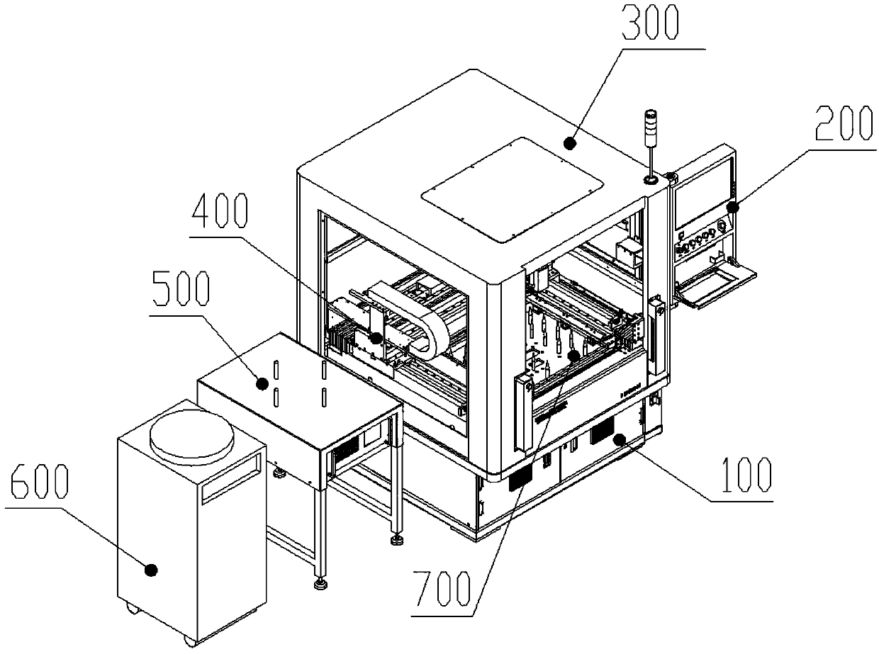
[0040] Please refer to figure 1 , figure 1 It is a schematic diagram of the overall structure of a specific embodiment provided by the present invention.

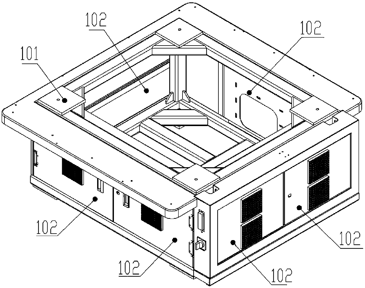
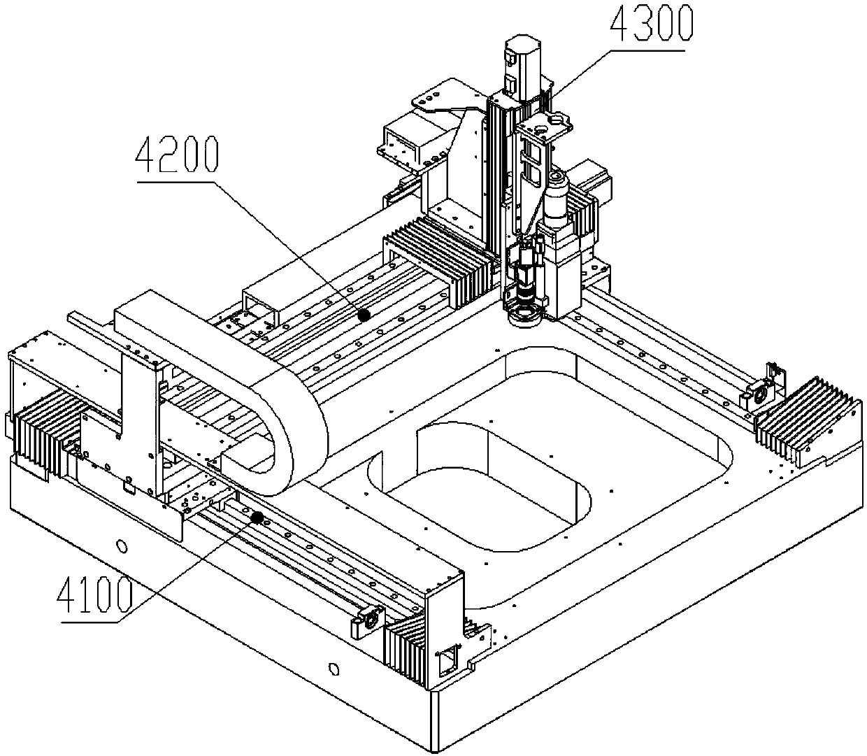
[0041] In a specific embodiment provided by the present invention, a laser cutting machine mainly includes a chassis assembly 100 , a gantry mechanism 400 , a fixture assembly 700 , a laser assembly 500 , a laser cutting head 4308 and a servo controller 801 .

[0042] Among them, the laser cutting head 4308...


PUM


Abstract

The invention discloses a laser cutting machine which comprises a bottom frame assembly, a gantry mechanism, a fixture assembly, a laser assembly, a laser cutting head and a follow-up controller. Thelaser assembly is used for providing a laser source for the laser cutting machine. The gantry mechanism comprises a Y-axis assembly, an X-axis assembly and a Z-axis assembly, wherein the Y-axis assembly, the X-axis assembly and the Z-axis assembly are used for driving the laser cutting head to move in the preset Y-axis direction, the X-axis direction and the Z-axis direction respectively. The follow-up controller is used for controlling the motion state of the Z-axis assembly, so that the distance from the bottom end of the laser cutting head to the surface of a workpiece is constant. In thisway, the laser cutting head is driven by the gantry mechanism to move during operation, so that the moving precision is high and the moving efficiency is high. Meanwhile, a plate workpiece is cut through laser, so that the incision is fine and smooth, burrs are basically avoided, and thus the burr removal process can be omitted, and the process flow is saved. In addition, the follow-up controllercontrols the laser cutting head to perform follow-up during operation, so that the cutting precision is greatly improved, and the special process machining on the plate workpiece is successfully realized.

Description

technical field [0001] The invention relates to the technical field of machining, in particular to a laser cutting machine. Background technique [0002] At present, LED substrates are commonly used with aluminum substrates, copper substrates, etc. The processing technology of aluminum substrates and copper substrates is basically the same, and the aluminum substrates are introduced below. Manufacturing process of aluminum substrate: material cutting→drilling→dry film optical imaging→board inspection→etching→etching inspection→green oil→characters→green inspection→tin spraying→aluminum base surface treatment→board punching→final inspection→packaging→shipping . Laser cutting will complete the "cutting", "drilling" and "punching" processes in the aluminum substrate manufacturing process. The processing methods used in the traditional "cutting", "drilling" and "punching" processes are: gong machining and punching. [0003] When machining the aluminum substrate, the thinner a...

Claims


Application Information

Patent Timeline
Patent Type & Authority Applications(China)
IPC IPC(8): B23K26/38B23K26/70B23K26/08
CPCB23K26/0884B23K26/38B23K26/702
Inventor 龚成万李斌吴佳霖张善基林克徐地明徐地华
Owner GUANGDONG ZHENGYE TECH
Why Eureka
Try Eureka