Eureka AIR delivers breakthrough ideas for toughest innovation challenges, trusted by R&D personnel around the world.

Variable gain amplifier

A gain amplifier and variable technology, applied in the direction of gain control, amplification control, electrical components, etc., can solve the problems of small gate variation range, complex amplifier switching circuit, large gain error, etc., and achieve good linear control characteristics and absolute Adjustable gain and low common mode noise

Active Publication Date: 2018-03-02
XIDIAN UNIV
View PDF7 Cites 9 Cited by
  • Summary
  • Abstract
  • Description
  • Claims
  • Application Information

AI Technical Summary

Problems solved by technology

Therefore, the dB linear variable gain amplifier implemented by CMOS technology generally needs to construct a pseudo-exponential function, the circuit is complex, the gain dynamic range is small, and the reliability is poor.
[0006] Southeast University's patent application "A dB Linear Variable Gain Amplifier Based on Exponential Function Approximation" (CN104135242A) uses the idea of ​​current complementarity to construct (1+x) / (1-x) function to achieve exponential control within a certain range , but the amplifier switching circuit is complex, consumes too much chip area and power consumption, and the dB linearity accuracy is low, and the gain error is large
[0007] Fudan University's patent application "a gain dB-linear realization method of a variable gain amplifier" (CN106026957A) is to generate a voltage that changes exponentially with the input linearly changing voltage through a MOS transistor working in the subthreshold region. The pole change range is small, and multiple auxiliary circuits are added, and the circuit structure is complex

Method used


Image

  • Variable gain amplifier
  • Variable gain amplifier
  • Variable gain amplifier

Examples


Embodiment Construction

[0035] The specific embodiments and effects of the present invention will be further described in detail below in conjunction with the accompanying drawings.

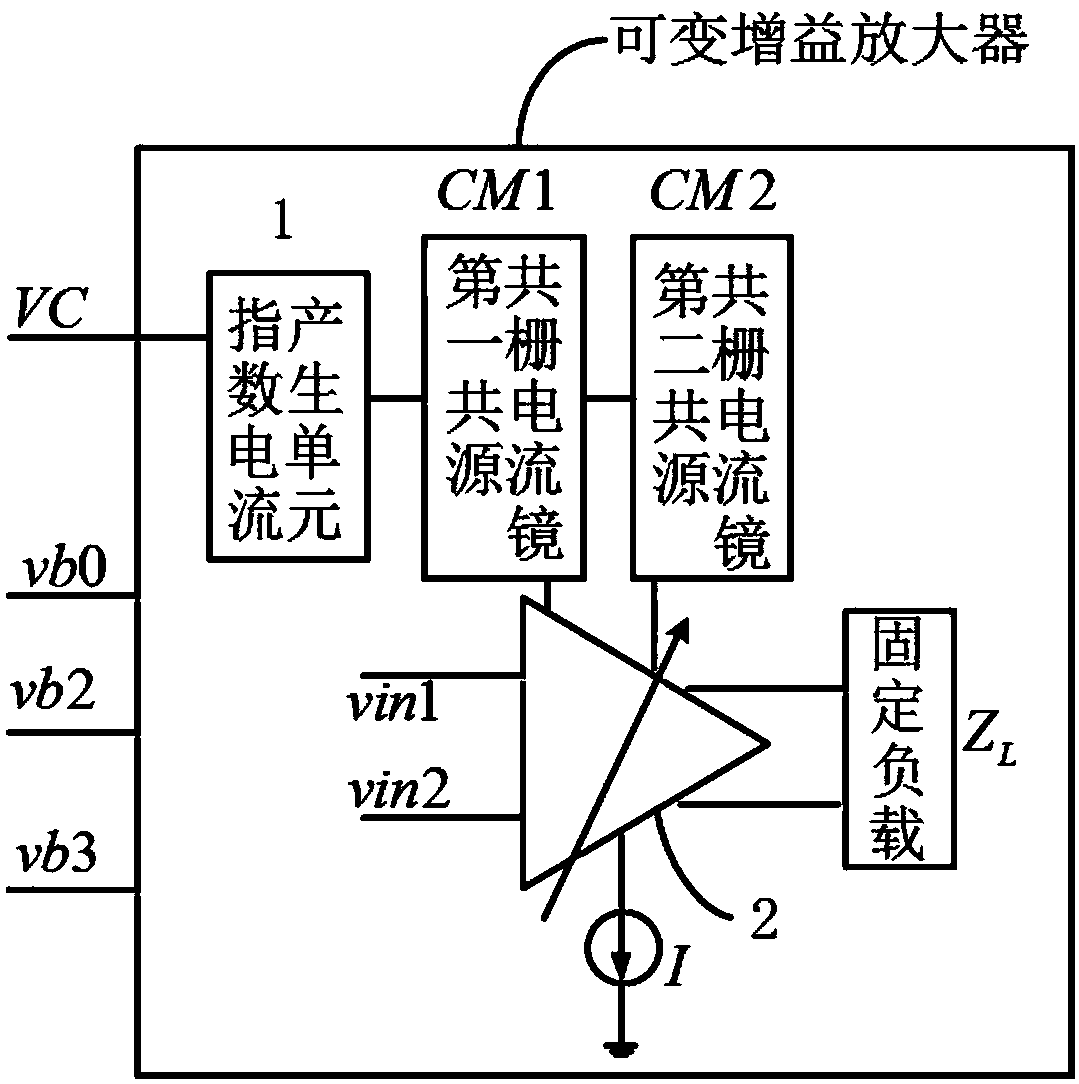
[0036] refer to figure 1 , the variable gain amplifier of the present invention includes an exponential current generating unit 1, a cascode current mirror CM, a current source I, a variable transconductance amplifying unit 2, and a fixed load Z L , the control voltage VC and three bias voltages, namely the first bias voltage vb0, the second bias voltage vb2 and the third bias voltage vb3, wherein the cascode current mirror CM includes the first cascode current mirror CM1 and the second cascode current mirror CM2.

[0037] The control voltage VC is connected to the input terminal of the exponential current generating unit 1 for controlling the output current of the exponential current generating unit 1 . The output terminal of the exponential current is connected to the variable transconductance amplification unit 2 t...


PUM


Abstract

The invention discloses a variable gain amplifier mainly solving the problems that the additional phase shifting of an existing variable gain amplifier is overlarge and a dB linear control circuit iscomplex. The variable gain amplifier comprises an index current generation unit (1), two cascade current mirrors, a current source I, a variable transconductance amplification unit (2), a fixing loadZL, a control voltage VC and three biasing voltages. The input end of the index current generation unit is connected with the control voltage VC, and the output end is connected with the variable transconductance amplification unit via the first cascade current mirror and the cascade current mirror to adjust a biasing current of a signal amplifying tube of the unit so as to change the equivalent transconductance of the same; a signal is amplified by the variable transconductance amplification unit, and is converted into an output signal while passing through a fixed load ZL. The variable gainamplifier has the advantages of simple structure of control circuit, high dB linear accuracy, small gain error, and extremely small phase fluctuation under different gain states, and can be applied tocommunication systems such as a wireless transceiver, a vector synthesizer and a phased array.

Description

technical field [0001] The invention belongs to the technical field of electronic circuits, in particular to a variable gain amplifier, which can be used in communication systems such as wireless transceivers, vector synthesizers, and phased arrays. Background technique [0002] In the receiver system, through the variable gain amplifier, the signal received by the antenna due to channel fading and whose power changes significantly can be converted into a signal with stable power. [0003] In the phased array system, the gain of the antenna array is adjusted by a variable gain amplifier. As an important component of the phased array system, when adjusting the gain of the RF front-end link, the change of the relative phase shift of each gain state must be small, otherwise the additional phase shift introduced by this stage will affect the entire phased array The phase accuracy of the system. [0004] In the automatic gain control system, the loop gain is changed by the vari...

Claims


Application Information

Patent Timeline
Patent Type & Authority Applications(China)
IPC IPC(8): H03G3/30
CPCH03G3/30
Inventor 李振荣王卓逸庄奕琪刘心彤
Owner XIDIAN UNIV
Why Eureka
Eureka Blog
Learn More