
Numerical control grinding machine

A CNC grinding machine and CNC system technology, applied in the direction of grinding machines, grinding bed, grinding machine parts, etc., can solve the problems of excessive dust, many adjustment elements, and low manual indexing accuracy of the universal dividing head.

Inactive Publication Date: 2018-03-06
钟泽
View PDF0 Cites 4 Cited by
  • Summary
  • Abstract
  • Description
  • Claims
  • Application Information

AI Technical Summary

Problems solved by technology

At present, the processing technology and process equipment used in domestic processing of similar workpieces are basically ground on ordinary tool grinders or spline shaft grinders with low automation. Simple Dresser Manual Dressing of Grinding Wheels
The manual indexing accuracy of the universal dividing head is low, and the quality of the manual dressing of the grinding wheel is poor, so that the groove formed by grinding cannot meet its technical requirements; at the same time, there are many adjustment elements during the dressing of the grinding wheel and grinding, which must be done manually, which is labor-intensive. Moreover, this kind of simple processing equipment has no dust-proof facilities, especially when dressing the grinding wheel, there is a lot of dust, and the working environment for workers is poor.

Method used


Image

  • Numerical control grinding machine
  • Numerical control grinding machine
  • Numerical control grinding machine

Examples


Embodiment Construction

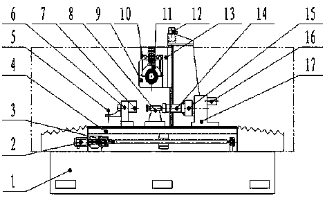
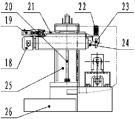
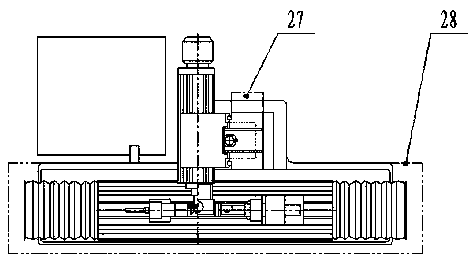
[0016] like figure 1 , figure 2 , image 3 Shown, the mechanical part of the present invention is made of bed 1, column 25, grinding head frame 13, tailstock 8, grinding head 9, workbench 4, emery wheel dresser 6, indexing mechanism 17 and claw chuck 15, sand Wheel shaft 24, exhaust dust removal system 27, semi-enclosed shield 28, cooling circulation system 26 and other components. A column 25 is fixedly installed on the bed 1, and the column 25 is connected with the grinding head frame 13 through the rolling linear guide rail and the ball screw rod 20; the grinding head frame 13 is connected with the grinding head 9 through the rolling linear guide rail 10 and the ball screw rod 1 21; The grinding wheel shaft 24 is installed in the head 9, and is connected to the grinding wheel 23 through the grinding wheel shaft 24. The grinding wheel shaft 24 is driven by the grinding head motor 18 to drive the grinding wheel 23 to do the main cutting movement; It is connected with th...


PUM


Abstract

The utility model relates to a numerical control grinding machine, which is used for forming and grinding the groove of the intermediate shaft of the ball cage coupling. The CNC system is respectively connected with the servo motor and the stepping motor. Servo motors 1, 2, and 3 are respectively installed on the grinding head frame, column, and bed base to realize the Z, Y, and X-direction linear motion of the CNC system. Servo motor 4 It is connected with the indexing mechanism to realize the numerical control indexing or axial rotation of the workpiece; the stepper motor is connected with the dresser to realize the rotary motion of the diamond pen; the grinding wheel shaft is driven by the grinding head motor to provide the main grinding movement; the machine tool has a semi-closed cover, Air extraction, dust removal and cooling circulation system; the servo motor is driven by a four-axis linkage numerical control system, and the stepping motor and the four-axis linkage numerical control system are controlled by a program controller; the invention is widely used in grinding various curved surfaces of metal parts. The movement and positioning of each part can be controlled by numerical control, with high degree of automation, high precision of grinding wheel dressing, smooth working surface and accurate indexing precision of workpieces, which can effectively improve the working environment and reduce the labor intensity of workers.

Description

technical field [0001] The invention relates to the technical field of mechanical processing equipment, in particular to a special numerically controlled grinding machine for channel forming of an intermediate shaft of a reinforced straight channel ball cage coupling. Background technique [0002] The two ends of the intermediate shaft of the reinforced straight channel ball cage coupling are designed with several straight channels parallel to the axis of the intermediate shaft as the inner sleeves of the two couplings. The cross-section of each channel is elliptical, and the steel ball corresponding to the coupling has two contact points, and the angle between the two contact points has special technical requirements. There are several different structural forms of such workpieces, the typical structure of which can be found in Figure 4 , Figure 5 , Image 6 , Figure 7 , Figure 8 . [0003] The grooves at both ends of the intermediate shaft are finally finished by ...

Claims


Application Information

Patent Timeline
IPC IPC(8): B24B19/06B24B53/075B24B41/02B24B41/06B24B47/04B24B55/06B24B55/02
CPCB24B19/06B24B41/02B24B41/06B24B47/04B24B53/075B24B55/02B24B55/06
Inventor 钟泽
Owner 钟泽
Learn More