Reflective optical pressure sensor

A pressure sensor and reflective technology, applied in the field of sensors, can solve the problems of inconvenient operation, inability to give full play to the advantages of optical pressure sensors, and small space, etc., and achieve the effect of simple operation, high reliability, and fewer optical path components

Inactive Publication Date: 2018-03-06
UNIV OF SHANGHAI FOR SCI & TECH
View PDF5 Cites 8 Cited by
  • Summary
  • Abstract
  • Description
  • Claims
  • Application Information

AI Technical Summary

Problems solved by technology

However, in the special environment where the space is small and the operation is inconvenient, the advantages of the light path transmission optical pressure sensor cannot be fully utilized.

Method used


Image

  • Reflective optical pressure sensor

Examples


Embodiment Construction

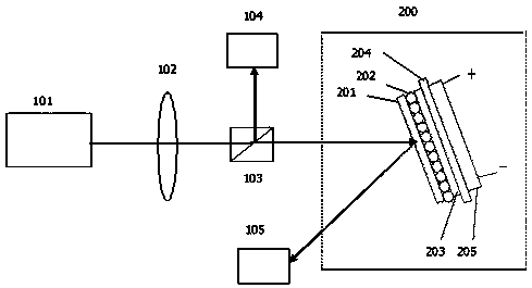
[0014] Such as figure 1 The schematic structural diagram of the reflective optical pressure sensor device shown includes a light source emitter 101; a lens 102; a beam splitter 103; a first light intensity detector 104; a second light intensity detector 105 and a detection unit 200, and the detection unit 200 includes from A glass sheet 201, a silicon dioxide sphere layer 202, a garnet 203, an aluminum film 204 grown on the garnet by magnetron sputtering, and a last layer of graphite 205 that are energized at both ends are sequentially laminated from top to bottom.

[0015] The laser output from the laser transmitter is focused and output by the lens 102 and then split by the beam splitter 103. One beam is reflected and directly received by the first light intensity detector 104, and the other beam is transmitted into the detection unit 200, and the incident light is obliquely incident on the detection unit. On the glass sheet 201, after penetrating the glass sheet 201, passin...


PUM

PropertyMeasurementUnit
wavelengthaaaaaaaaaa
diameteraaaaaaaaaa
thicknessaaaaaaaaaa

Abstract

The invention relates to a reflective optical pressure sensor. Laser output by a laser emitter is output by a lens in a focused manner and is then split by a beam splitting device. One beam is reflected and is absorbed directly by a first light intensity detector. The other beam is transmitted to a detection unit. An incoming light beam casts to a glass sheet of the detection unit in an inclined manner, penetrates through the glass sheet and then a silicon dioxide globule layer and a garnet in sequence, and then is reflected by an aluminum film on the back of the garnet. The reflection light passes through the garnet and the silicon dioxide globule layer again and is then output from the glass sheet. The reflection light is received by a second light intensity detector after being output.Graphite electrification voltage change of the detection unit causes heat deformation of the silicon dioxide globule layer in the detection unit, so that light intensity of reflection light of the detection unit changes. Through comparing the light intensity change relation of the two light intensity detectors, a pressure parameter can be acquired. The sensor provided by the invention has advantages of small element quantity, high reaction speed, high reliability, high adaptability, simple operation, high precision and the like.

Description

technical field [0001] The invention relates to a sensor technology, in particular to a reflective optical pressure sensor with fast response and high precision. Background technique [0002] Due to the fast response speed, the photoelectric sensor can realize non-contact measurement, high precision, high resolution, good reliability, small size, light weight, low power consumption, and easy integration. It is widely used in military, aerospace, communication, detection and industrial automation. It is widely used in various fields such as control. At present, the development in the field of photoelectric sensing can be divided into two directions: principle research and application development. With the gradual maturity of photoelectric technology, the practical development of photoelectric sensors has become a hot spot and key to the development of the entire field. [0003] A photoelectric sensor generally consists of three parts: a light source, an optical path, and a ...

Claims


Application Information

Patent Timeline
Patent Type & Authority Applications(China)
IPC IPC(8): G01L1/24G01L11/02
CPCG01L1/24G01L11/02
Inventor 高文强潘倩赵新未沈世华郝蕊蕊柏雪焦新兵
Owner UNIV OF SHANGHAI FOR SCI & TECH
Why Eureka
Try Eureka