
Coupling focal length press machine

A press and focal length technology, applied in the field of optical communication, can solve the problems of poor crimping accuracy, poor precision, poor crimping accuracy, etc., and achieve the effects of stable optical signal indicators, high pressing efficiency and stable quality

Inactive Publication Date: 2018-03-06
韩海威
View PDF0 Cites 0 Cited by
  • Summary
  • Abstract
  • Description
  • Claims
  • Application Information

AI Technical Summary

Problems solved by technology

[0004] The technical problem to be solved by the present invention is that the traditional crimping equipment has complex structure, and the precision of crimping is poor, and it cannot be automatically coupled, so that the signal of the optical signal converted into the optical fiber or cable is poor, which affects the communication quality. The purpose is to provide a A coupling focal length press machine, which solves the problem that the traditional crimping equipment has a complex structure, and the accuracy of crimping is poor, and it cannot be automatically coupled, so that the signal of the optical signal converted from electricity into the optical fiber or cable is poor, which affects the communication quality.
The invention is suitable for press-fitting the LD chip and the housing in the optical communication industry, so that the optical signal converted into electricity enters the optical fiber or optical cable, and the optical signal is transmitted through the optical fiber or optical cable. Through automatic coupling, the laser optical signal and the The automatic press-fitting machine that completes press-fitting, counting, and timing of optical fiber docking has a simple structure and solves the problem of complex structure of traditional crimping equipment, and the precision of crimping is poor, so it cannot be automatically coupled, so that the optical signal converted into electricity enters the optical fiber or cable. Poor signal, which affects the quality of communication

Method used

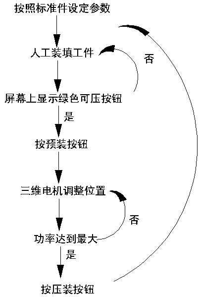
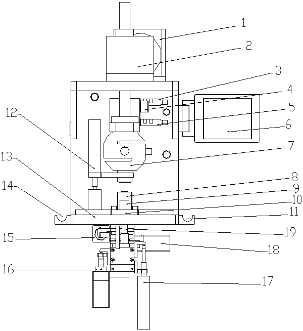
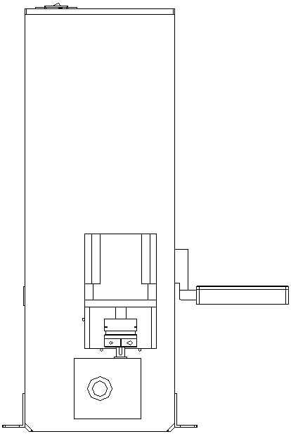

Image

  • Coupling focal length press machine
  • Coupling focal length press machine
  • Coupling focal length press machine

Examples


Embodiment

[0017] Such as figure 1 , figure 2 , image 3 As shown, a coupling focal length press includes an inner hollow shell, on which a first stepping motor 2 is arranged, and the first stepping motor 2 is connected with a spiral lifting rod 1, and one end of the spiral lifting rod 1 is arranged on In the housing, a limit switch, a pressure sensor 7 and a grating ruler 12 are arranged in the housing, and the limit switch, the pressure sensor 7 and the grating ruler 12 are all fixed on the part where the spiral lifting rod 1 is arranged in the housing, and the pressure sensor 7 is arranged on Below the limit switch, the connection between the grating ruler 12 and the spiral lifting rod 1 is located below the pressure sensor 7, and a grooved workbench 10 and a console 13 are installed in the housing, and the grooved workbench 10 and the console 13 are both arranged on the Below the pressure sensor 7, an indenter 9 and a tooling 8 are arranged above the trough workbench 10, the tooli...


PUM


Abstract

The invention discloses a coupled focal length press. The casing is provided with an active power mechanism connected with a lifting device, a limit switch, a pressure sensor and a grating ruler are arranged in the casing, and a workbench and a console are installed in the casing. , the pressure head and tooling are set above the workbench, the tooling is fixed to the workbench, the pre-press switch and the push switch are set on the console, the connecting mechanism is set under the workbench, and three auxiliary power mechanisms are set under the connecting mechanism; The switch includes an upper limit switch and a lower limit switch; a touch head is installed on the lifting device, and a display screen is installed on the casing. The press completes pressing, counting, and timing through automatic coupling, that is, the docking of the laser optical signal and the optical fiber. The pressing efficiency is high. The automatic coupling can realize arbitrary setting of relatively fixed optical signals entering the optical fiber. The quality of the installation is stable, so that the electrical conversion of the optical signal into the optical fiber or cable is stable.

Description

technical field [0001] The invention belongs to the field of optical communication, and in particular relates to a coupling focal length press. Background technique [0002] Optical fiber communication is to use optical fiber to transmit light waves carrying information to achieve the purpose of communication. To make the light wave a carrier of information, it must be modulated, and then the information is detected from the light wave at the receiving end. As a technology, optical fiber communication has a history of only 30 to 40 years since its appearance and development. However, it has brought about tremendous changes to the world's communication landscape, and its profound and long-term impact may still be behind. Optical fiber communication is the main transmission means of modern communication network. Its development history is only 10 or 20 years, and it has gone through three generations: short-wavelength multimode fiber, long-wavelength multimode fiber and long-...

Claims


Application Information

Patent Timeline
Patent Type & Authority Applications(China)
IPC IPC(8): G02B6/42B30B9/00
CPCG02B6/4201B30B9/00
Inventor 韩海威
Owner 韩海威
Learn More