


Quick Research
Generate reliable direction feasibility study reports for your R&D in just a few steps.

Technical Q&A
Discover and master advanced knowledge NOW. Basics, ideas, possibilities, all at once.

Find Solutions
As an expert in R&D theories, this can generate solutions to your technical problems instantly.

Evaluate Feasibility
Analyze your overall solution with one click, know your potential R&D risks in advance.

Monitor Landscape
Get weekly tech updates, stay abreast of the latest tech innovations and key insights.
Inner-core-free thrombolytic catheter
A thrombolysis and catheter technology, applied in the field of medical thrombolysis catheters and coreless thrombolysis catheters, can solve the problems of increasing the bleeding risk of patients, increasing the medical expenses of patients, etc., achieving good thrombosis prevention, reducing space-occupying effect, The effect of preventing solidification
- Summary
- Abstract
- Description
- Claims
- Application Information
AI Technical Summary
Problems solved by technology
Method used
Image

Examples
Embodiment 1
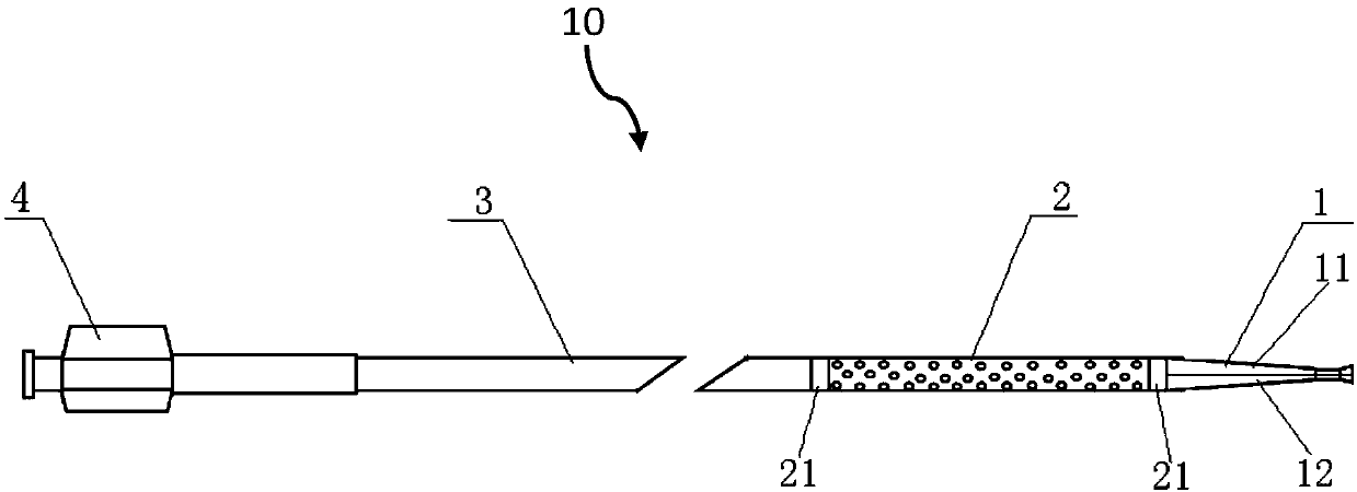
[0022] figure 1 It is a structural schematic diagram of the coreless thrombolytic catheter of the present invention.
[0023] Such as figure 1 As shown, the coreless thrombolytic catheter 10 of the present invention (hereinafter referred to as the thrombolytic catheter) 10 has a tubular shape as a whole, and includes a connection end 4 , a delivery section 3 , a perfusion section 2 and a head end 1 in sequence.
[0024] The outer wall of the connection end 4 has a threaded structure for connecting with the drug delivery device; the delivery section 3 is used to deliver the thrombolytic drug pumped into the drug delivery device; the wall of the perfusion section 2 has a through structure for the thrombolytic drug to release. In this embodiment, the length of the perfusion section 2 is 30 cm, and the penetrating structure on the wall is a plurality of through holes formed by laser engraving; the outer diameter of the delivery section 3 and the perfusion section 2 is the same, ...
Embodiment 2
[0035] In the second embodiment, the same numbers are assigned to the same structures as those in the first embodiment, and the same descriptions are omitted.
[0036] In this embodiment, the total length of the thrombolysis catheter 10 is about 150 cm; the length of the perfusion section 2 is 30 cm, and the wall is provided with a penetrating crack structure formed by laser engraving. The outer diameters of the delivery section 3 and the perfusion section 2 are the same, which is 3F.
[0037] The application of the thrombolysis catheter of this embodiment will be described below with reference to the accompanying drawings.
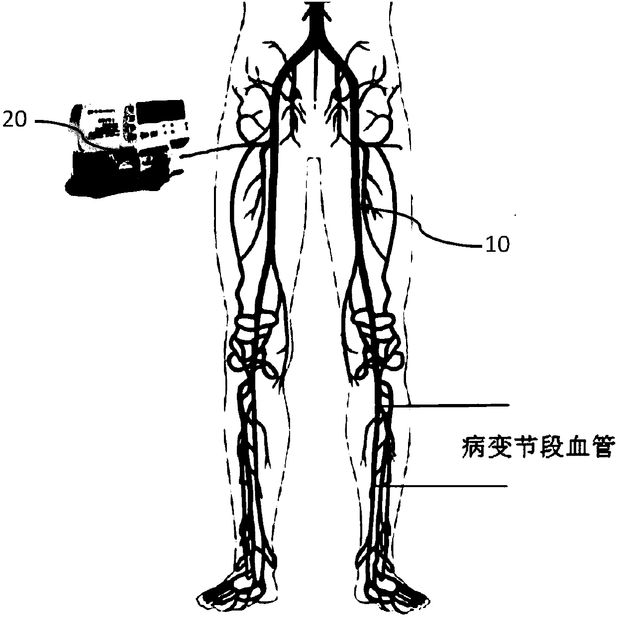
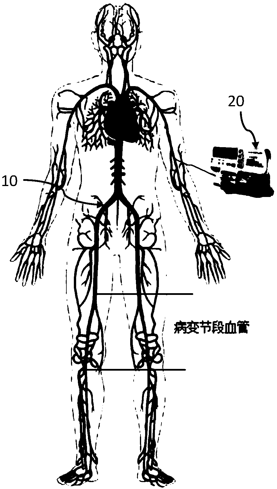
[0038] image 3 It is a schematic diagram of the application of the coreless thrombolytic catheter according to the second embodiment of the present invention.
[0039] Such as image 3 As shown, the patient involved in this case was a patient with stenosis and thrombosis of the right femoropopliteal artery. Examination revealed that a large number of ...
PUM
| Property | Measurement | Unit |
|---|---|---|
| Length | aaaaa | aaaaa |
| Outer diameter | aaaaa | aaaaa |
Abstract
Description
Claims
Application Information
 - R&D Engineer
- R&D Manager
- IP Professional
- Industry Leading Data Capabilities
- Powerful AI technology
- Patent DNA Extraction
Browse by: Latest US Patents, China's latest patents, Technical Efficacy Thesaurus, Application Domain, Technology Topic, Popular Technical Reports.
© 2024 PatSnap. All rights reserved.Legal|Privacy policy|Modern Slavery Act Transparency Statement|Sitemap|About US| Contact US: help@patsnap.com