Sintering ore grate furnace cooling and waste heat utilization device and waste heat utilization method

A technology of sinter and grate furnace, which is applied in the fields of sinter grate furnace cooling, waste heat recovery device and waste heat utilization, which can solve the waste of waste gas and waste heat resources, reduce energy consumption, avoid air leakage, and increase air permeability Effect

Pending Publication Date: 2018-03-13
ZHONGYE-CHANGTIAN INT ENG CO LTD
View PDF9 Cites 1 Cited by
  • Summary
  • Abstract
  • Description
  • Claims
  • Application Information

AI Technical Summary

Problems solved by technology

[0005] The technical problem to be solved by the present invention is: Aiming at the air leakage of the cooler, the waste of waste gas waste heat resources and environmental pollution in the prior art, and the high power consumption of the vertical tank cooling blower, the present invention provides a sinter grate Furnace cooling and waste heat recove

Method used


Image

  • Sintering ore grate furnace cooling and waste heat utilization device and waste heat utilization method
  • Sintering ore grate furnace cooling and waste heat utilization device and waste heat utilization method
  • Sintering ore grate furnace cooling and waste heat utilization device and waste heat utilization method

Examples


Embodiment 1

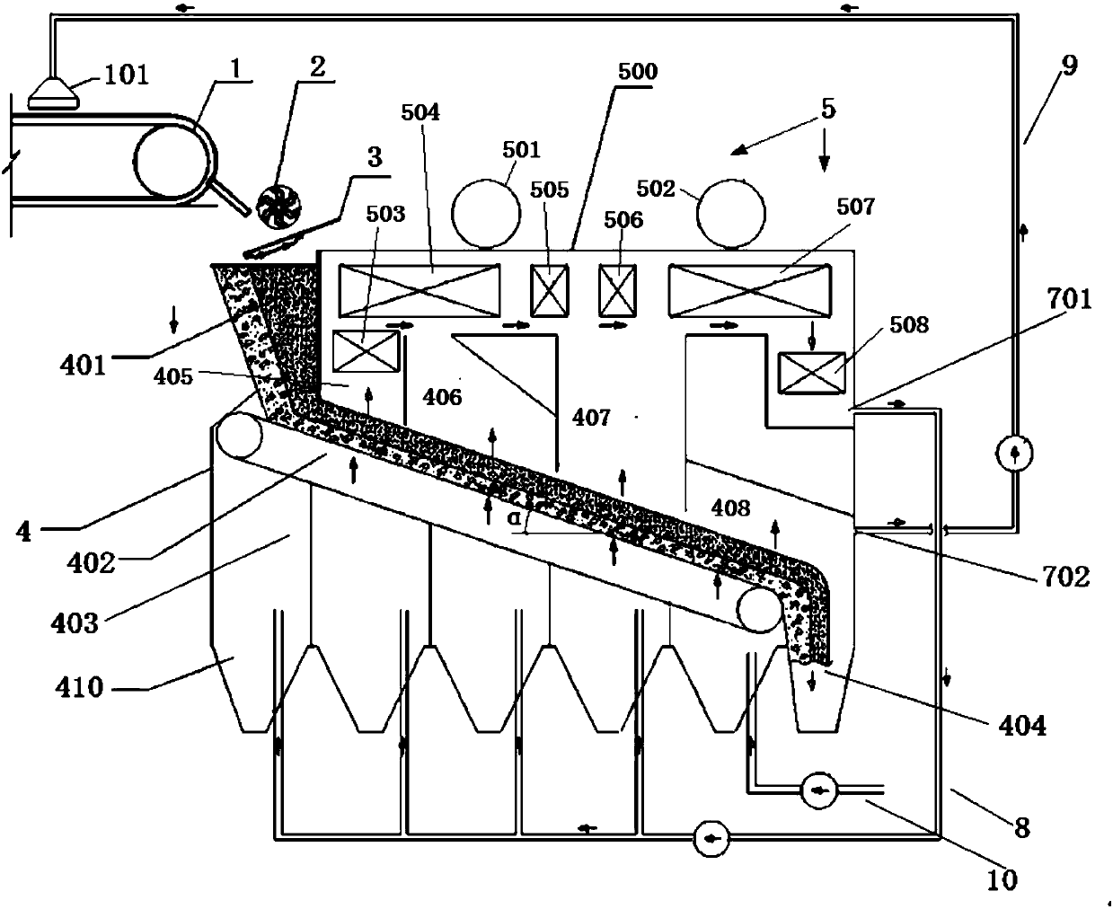
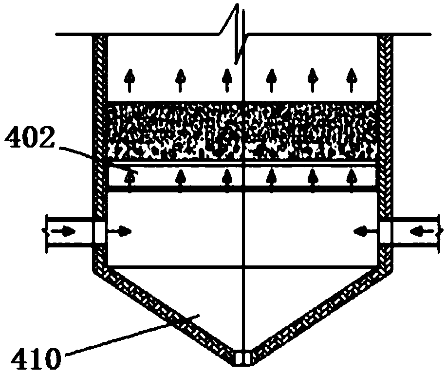
[0079] A sinter grate furnace cooling and waste heat utilization device, the device is sequentially provided with a sintering machine 1, a crusher 2, a hot screen 3, and a grate furnace 4. The grate furnace 4 includes a feed port 401 , a fire grate 402 , an air inlet chamber 403 , and a discharge port 404 . Wherein, the front end of the fire grate 402 is provided with a feed port 401 , and the feed port 401 is connected and communicated with the fire grate 402 . The end of the fire grate 402 is provided with a discharge port 404 , and the discharge port 404 is connected and communicated with the fire grate 402 . The bottom of the fire grate 402 is provided with an air inlet cavity 403 ; the top of the fire grate 402 is provided with a waste heat utilization device 5 . Crusher 2 is a single roll crusher. The grate 402 is a chain grate.

[0080] The top of the grate 402 is divided into four cavities. Along the running direction of the grate, there are first cavity 405 , seco...

Embodiment 2

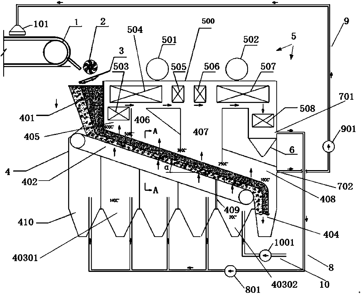
[0084] Embodiment 1 is repeated, except that a dust collector 6 is provided below the low-parameter economizer 508, and the dust collector 6 is a gravity dust collector.

Embodiment 3

[0086] Embodiment 2 is repeated, except that a partition 409 is provided in the air inlet cavity 403 . The partition 409 divides the air inlet cavity 403 into an exhaust gas inlet 40301 and an air inlet 40302 . The width of the waste gas inlet 40301 accounts for 70% of the entire air inlet cavity 403 .

[0087] The inlet of the first waste gas pipeline 8 is connected to the first high-temperature waste gas outlet 701 . The outlet of the first exhaust gas pipeline 8 is connected to the exhaust gas inlet 40301 . A circulating fan 801 is provided on the first waste gas pipeline 8 . The device also includes a second exhaust gas duct 9 . A second high-temperature exhaust gas outlet 702 is provided in the fourth cavity 408 . A wind cover 101 is provided above the sintering machine 1 . The inlet of the second waste gas pipeline 9 is connected to the second high-temperature waste gas outlet 702 in the fourth cavity. The outlet of the second waste gas pipe 9 is connected to the w...


PUM

PropertyMeasurementUnit
Thicknessaaaaaaaaaa

Abstract

The invention relates to a sintering ore grate furnace cooling and waste heat utilization device and waste heat utilization method. The device is sequentially provided with a sintering machine (1), acrusher (2), a hot screen (3) and a grate furnace (4). The grate furnace (4) comprises a feeding opening (401), a fire grate (402), air inlet cavities (403) and a discharging opening (404). High-temperature waste gas above the fire grate is recycled to be utilized through the waste heat utilization device, the utilized waste gas enters the air inlet cavities below the fire grate or an air cover ofthe sintering machine, and a cycle is formed. According to the device and waste heat utilization method, the problems of cooling machine air leaking, waste gas waste heat resource waste and environment pollution in the prior art can be solved, the problem of high power consumption of a vertical tank type cooling air blower can be reduced, and total utilization of sintering ore waste gas waste heat resources can be achieved.

Description

technical field [0001] The invention mainly relates to the technical fields of waste heat utilization and environmental protection in sintering process, and in particular to a sinter grate furnace cooling and waste heat recovery device and a waste heat utilization method. Background technique [0002] At present, the cooling of sinter in domestic iron and steel enterprises usually adopts ring cooler or belt cooler, blower type cooling, the ring cooler trolley moves horizontally, and the wind blown by the blower cools the ore vertically upwards, so that the sinter is cooled to 150 Below ℃ for the next process. The heat exchange between sinter and cooling air in belt cooling or annular cooler belongs to cross-flow heat exchange. The thickness of the feeding layer of the annular cooler trolley is generally 1400mm, and the cooling air volume per ton of ore is generally 2200Nm 3 / t, the material layer resistance is generally 3000Pa. Because there is a gap between the trolley an...

Claims


Application Information

Patent Timeline
IPC IPC(8): F27D15/02F27D17/00
CPCF27D15/0213F27D17/004Y02P10/25
Inventor 徐忠
Owner ZHONGYE-CHANGTIAN INT ENG CO LTD
Why Eureka
Try Eureka