Optical fiber dynamic light scattering detection device for high-concentration particle swarms

A technology of dynamic light scattering and detection devices, which is applied to measuring devices, particle and sedimentation analysis, particle size analysis, etc., can solve the problems of the signal-to-noise ratio of scattered light measurement signals, the quality of correlation functions, and the large volume of measuring devices, etc., to achieve The effect of shortening the optical path, small scale, and reducing the scattering volume

Inactive Publication Date: 2018-03-13
HUAZHONG UNIV OF SCI & TECH
View PDF8 Cites 5 Cited by
  • Summary
  • Abstract
  • Description
  • Claims
  • Application Information

AI Technical Summary

Problems solved by technology

[0004] The traditional dynamic light scattering detection method has a large measuring device, and it is easy to cause multiple scattering when measuring high-concentration samples
And because the scattered light is transmitted in the air, it is easily disturbed by dust, external light and vibration, resulting in a decrease in the signal-to-noise ratio of the scattered light measurement signal, resulting in a decrease in the quality of the correlation function, limiting the measurement accuracy, and affecting the measurement results

Method used


Image

  • Optical fiber dynamic light scattering detection device for high-concentration particle swarms
  • Optical fiber dynamic light scattering detection device for high-concentration particle swarms
  • Optical fiber dynamic light scattering detection device for high-concentration particle swarms

Examples


Embodiment Construction

[0026] In order to make the object, technical solution and advantages of the present invention clearer, the present invention will be further described in detail below in conjunction with the accompanying drawings and embodiments. It should be understood that the specific embodiments described here are only used to explain the present invention, not to limit the present invention. In addition, the technical features involved in the various embodiments of the present invention described below can be combined with each other as long as they do not constitute a conflict with each other.

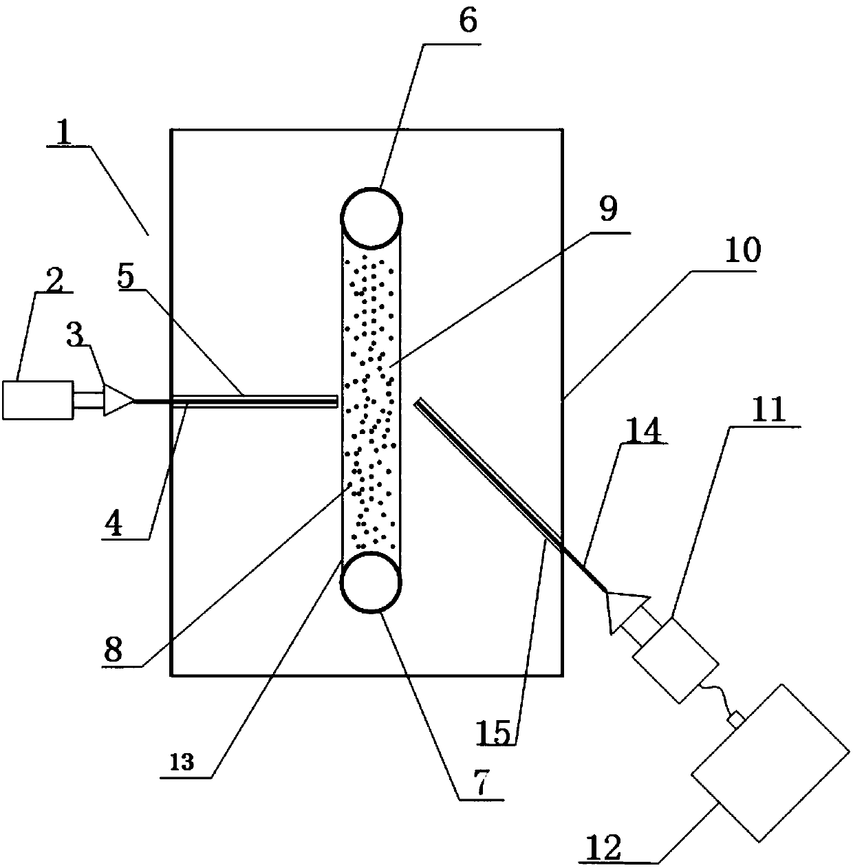
[0027] The present invention provides an optical fiber dynamic light scattering detection device for high-concentration particle groups. The dynamic light scattering measurement device includes a laser 2, an optical fiber coupler 3, a transmitting optical fiber 4, a receiving optical fiber 14, a microfluidic chip 10, a photodetector 11 and digital correlator 12.

[0028] Wherein, the microfluid...


PUM


Abstract

The invention discloses an optical fiber dynamic light scattering detection device for high-concentration particle swarms, and belongs to the field of photoelectric detection. The optical fiber dynamic light scattering detection device comprises a laser device, an optical fiber coupler, a transmitting optical fiber, a receiving optical fiber, a micro-fluidic chip, a photoelectric detector and a digital correlator. The micro-fluidic chip is provided with a micro-channel, the micro-channel is used as a sample pool, the laser device is used for transmitting coherent light, the transmitting optical fiber is connected with a laser source by the optical fiber coupler, the coherent light can be coupled by the optical coupler to be transmitted into the sample pool via the transmitting optical fiber, can be transmitted through the high-concentration particle swarms, with the to-be-measured particle sizes, in the sample pool and then is scattered, scattered light can be transmitted through the receiving optical fiber and can be transmitted into the photoelectric detector via the optical fiber coupler, and the digital correlator is connected with the photoelectric detector and is used for acquiring light intensity autocorrelation functions according to photoelectrons obtained by the photoelectric detector. The optical fiber dynamic light scattering detection device has the advantages thatthe particle sizes of the high-concentration particle swarms can be measured by the optical fiber dynamic light scattering detection device in an in-situ manner, the optical fiber dynamic light scattering detection device is small, is low in sample consumption and can be applied to measuring the particle sizes of the high-concentration particle swarms, and light-resistant designs and temperaturecontrol can be facilitated.

Description

technical field [0001] The invention belongs to the field of photoelectric detection, and more specifically relates to an optical fiber dynamic light scattering detection device for high-concentration particle groups. Background technique [0002] The particle size and distribution of submicron and nano-particles are the main parameters to characterize their performance, so the measurement of these parameters is of great significance. Dynamic light scattering technology does not require fluorescent labeling of samples, and is the only particle size analysis technology that can realize liquid biopsy, and dynamic light scattering technology is an effective method for measuring the particle size of submicron and nano particles. [0003] In the dynamic light scattering particle measurement technology, photon correlation spectroscopy is widely used. This method uses a photodetector to receive scattered light at a fixed spatial position for detection. However, due to the extremel...

Claims


Application Information

Patent Timeline
Patent Type & Authority Applications(China)
IPC IPC(8): G01N15/02
CPCG01N15/0211
Inventor 夏珉张盼杨克成李微
Owner HUAZHONG UNIV OF SCI & TECH
Why Eureka
Try Eureka