

Hemodialysis catheter
A technology of hemodialysis tube and dialysis unit, which is applied in the field of hemodialysis tube, can solve problems such as unstable blood pressure, large dialysis equipment, death, etc., and achieve the effect of avoiding invasive injury, increasing dialysis area, and improving dialysis efficiency
- Summary
- Abstract
- Description
- Claims
- Application Information
AI Technical Summary
Problems solved by technology
Method used
Image

Examples
Embodiment 1
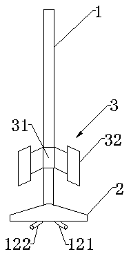
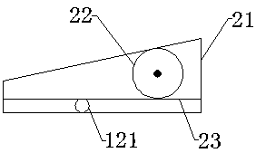
[0037] Such as Figure 1-3 As shown, the present embodiment provides a hemodialysis tube, which includes a dialysis part 1 , a connection part 2 connected to the dialysis part 1 , and a fixing part 3 disposed between the dialysis part 1 and the connection part 2 .
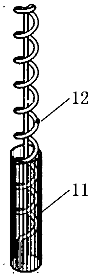
[0038] The dialysis unit 1 includes a dialysis outer tube 11 , a dialysis inner tube 12 and a dialysis membrane. Dialysis outer tube 11 is sleeved on the outer periphery of dialysis inner tube 12. There is a gap between dialysis outer tube 11 and dialysis inner tube 12 to facilitate blood circulation. Dialysis outer tube 11 is hollowed out so that blood enters dialysis outer tube 11 and dialysis tube 12. The space between the inner tubes 12. The dialysis membrane is wrapped on the outer wall of the dialysis inner tube 12, and the dialysis inner tube 12 can be considered to support the dialysis membrane or shape the dialysis membrane. The dialysate flows through the inner dialysis tube 12, and the dialysis part 12...
Embodiment 2
[0045] This embodiment provides a polytetrafluoroethylene-polyurethane-nano-silver composite material and its preparation method. The polytetrafluoroethylene-polyurethane-nano-silver composite material has good biocompatibility and antibacterial properties, and it is used for hemodialysis The built-in dialysis tubing has a good application prospect. This polytetrafluoroethylene-polyurethane-nano-silver composite material is prepared through the following steps:
[0046] Step 1: Weigh 54g of polytetrafluoroethylene concentrated dispersion, 38g of diisocyanate, and 14g of polycaprolactone diol, stir and mix and heat to 80°C, add 0.08g of 1,4-butanediol and stannous octoate to it 0.06g, continue to stir and maintain the heating temperature for 3 hours, then raise the temperature to 90°C, and add 0.13g of trimethylolpropane monoallyl ether to continue the reaction for 3 hours, and the polytetrafluoroethylene-polyurethane composite material can be obtained.
[0047] Step 2: The po...
PUM
 Abstract
Description
Claims
Application Information