Radiant tube of quick pyrolyzing furnace without heat carriers

A radiant tube and pyrolysis furnace technology, applied in the field of gas-fired radiant tubes, can solve the problems of reduced heat transfer efficiency, easy material accumulation, and large material obstruction effect, so as to achieve the advantages of increasing the area, increasing the heat transfer area, and increasing the effect of distribution. Effect

Pending Publication Date: 2018-03-16
SHENWU TECH GRP CO LTD
View PDF0 Cites 0 Cited by
  • Summary
  • Abstract
  • Description
  • Claims
  • Application Information

AI Technical Summary

Problems solved by technology

However, at present, the circular structure is adopted on the outside of the radiant tube, which has the following disadvantages: it ha

Method used


Image

  • Radiant tube of quick pyrolyzing furnace without heat carriers
  • Radiant tube of quick pyrolyzing furnace without heat carriers

Examples


Embodiment 1

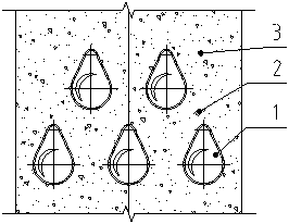
[0039] The radiant tubes of the present invention are staggeredly arranged in the hearth of an experimental furnace, and the experiment of coal powder particles is carried out on the experimental furnace.

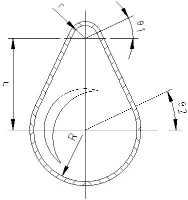
[0040] The uniformity of the cloth is measured by measuring the height of the falling material layer, the particle size is 1mm, and the particle bulk density is 1.0kg / cm 3 , r=25mm, R=100mm, h=180mm (h is the distance between the upper and lower fan-shaped centers), the experimental results are as follows: the material accumulation height at the upper end of the radiant tube is much smaller than that of the ordinary radiant tube, and the maximum thickness of the blanking layer is higher than the minimum thickness High 3 ~ 5%, basically achieve uniform cloth.

[0041] In summary, the reduced upper section of the radiant tube of the present invention reduces the hindrance of the radiant tube to the falling materials, which can better increase the cloth distribution effect an...


PUM


Abstract

The invention relates to a radiant tube of a fast pyrolysis furnace without a heat carrier, comprising a lower fan-shaped part, a connecting part and an upper fan-shaped part, wherein the radius R of the lower fan-shaped part is greater than the radius r of the upper fan-shaped part; A connecting portion is provided between the lower fan-shaped part and the upper fan-shaped part, so that the cross section of the radiant tube is drop-shaped; the central angle of the arc of the upper fan-shaped part is 180°‑2θ1, 10°≤θ1≤70 °; the central angle of the arc of the lower sector is 180°+θ2, 10°≤θ2≤70°. The reduced upper section of the radiant tube reduces the resistance of the radiant tube to the falling material, which can better increase the cloth effect and make the cloth more uniform.

Description

technical field [0001] The invention belongs to the field of gas radiant tubes, in particular to a radiant tube for a fast pyrolysis furnace without a heat carrier. Background technique [0002] The non-heat carrier fast pyrolysis furnace is a kind of heat exchange equipment that works according to the principle of countercurrent, and the material going down and the airflow in the furnace perform strong convective heat exchange. The working process is to load the material into the furnace through the material distribution equipment on the top of the furnace, the material falls continuously in the way of free fall, and the hot gas exchanges heat with the solid particles from top to bottom to heat the material. [0003] During the falling process, the material will pass through the radiant tube lying across the furnace, and the shape of the radiant tube has a particularly important influence on the uniformity of the material distribution and the heating efficiency of the desce...

Claims


Application Information

Patent Timeline
IPC IPC(8): C10B53/04C10B47/00F23D14/12
CPCC10B53/04C10B47/00F23D14/12F23D2900/1412
Inventor 常胜良李生忠林景龙吴道洪
Owner SHENWU TECH GRP CO LTD
Why Eureka
Try Eureka