
Base station antenna and isolation plate thereof

A base station antenna and isolation plate technology, which is applied to antennas, antenna parts, antenna supports/installation devices, etc., can solve problems such as limiting the cross-polarization discrimination rate of base station antennas, port isolation deterioration, and pattern deformation, and avoid Sharp deterioration of cross-polarization, reduced antenna weight, improved port isolation effect

Pending Publication Date: 2018-03-20
TONGYU COMM INC
View PDF0 Cites 5 Cited by
  • Summary
  • Abstract
  • Description
  • Claims
  • Application Information

AI Technical Summary

Problems solved by technology

[0003] Due to the limitation of the size of the radome and the reflector of the base station antenna, it is often difficult to achieve a safe isolation distance between the radiating elements. Superposition with the incident wave leads to serious deformation of the pattern
[0004] In addition, electromagnetic waves scatter and resonate through metal boundaries such as reflectors and partitions. On the one hand, it leads to beam skew, deformation, and grating lobes. On the other hand, the cross-polarized components contained in stray electromagnetic waves seriously reduce the noise immunity of the antenna. and cross-polarization discrimination rate, thus affecting the signal transceiver sensitivity and communication rate
At present, the lack of effective isolation means has become a technical bottleneck that limits the cross-polarization discrimination rate of base station antennas and uses polarization diversity for wireless communication expansion.

Method used


Image

  • Base station antenna and isolation plate thereof
  • Base station antenna and isolation plate thereof
  • Base station antenna and isolation plate thereof

Examples


Embodiment Construction

[0024] The present invention will be described in detail below in conjunction with the accompanying drawings and embodiments.

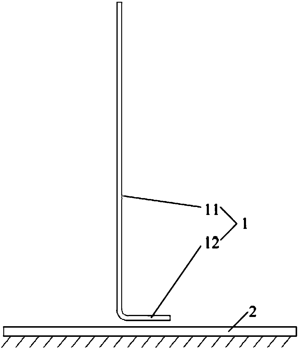
[0025] combine Figure 1 to Figure 4 For reference, the present invention provides a separator. The isolation plate 1 is a thin metal plate, such as a copper thin plate. The thin metal plate 1 is roughly in the shape of a strip, and more than one hollowed-out wave-transmitting window 121 and more than one hollowed-out resonance slot 122 are arranged along the length direction of the thin metal plate 1 . Wherein, each wave-transmissive window 121 and each resonant slot 122 can be arranged correspondingly according to the formation form of the antenna array.

[0026] Specifically, each wave-transmissive window 121 is composed of more than one vertical slit 1211 formed along the height direction of the metal sheet 1. The vertical slit 1211 means that the opening direction of the slit is in the vertical direction (that is, along the height direction), ...


PUM


Abstract

The invention discloses an isolation plate. The isolation plate is a metal sheet; one or more hollow transparent windows and one or more hollow resonant tanks are arranged along the length direction of the metal sheet; each transparent window is formed by one or more vertical slots formed through processing along the height direction of the metal sheet; and each resonant tank is formed by one or more horizontal gaps formed through processing along the length direction of the metal sheet. The invention further discloses a base station antenna. Through the isolation plate, no significant effectis generated on a directional diagram of a high-frequency oscillator while isolation of a low-frequency oscillator can be improved; and rapid deterioration of cross polarization caused by scattering and resonance is avoided while isolation of a port is improved.

Description

technical field [0001] The invention relates to a base station antenna and an isolation board thereof. Background technique [0002] Port isolation and cross-polarization discrimination are important technical indicators of base station antennas. Improving port isolation and cross-polarization discrimination is of great significance for enhancing the anti-interference ability of base station antennas, improving receiving sensitivity, giving full play to channel capacity, and increasing wireless data transmission rates. important meaning. [0003] Due to the limitation of the size of the radome and the reflector of the base station antenna, it is often difficult to achieve a safe isolation distance between the radiation units. The mutual reception and secondary radiation between the oscillators not only deteriorate the port isolation, but more seriously, secondary radiation and scattering pass through The superposition with the incident wave leads to serious deformation of t...

Claims


Application Information

Patent Timeline
IPC IPC(8): H01Q1/24H01Q1/50H01Q21/24
CPCH01Q1/246H01Q1/50H01Q21/24
Inventor 岳彩龙丁文吴中林方铁勇付聪曹林利张理栋
Owner TONGYU COMM INC
Learn More