
Free-form surface machining method and device based on two-step online detection and compensation technology

A curved surface processing and free technology, applied in the direction of auxiliary devices, metal processing equipment, manufacturing tools, etc., can solve the problems of long time consumption and fluctuation of online detection, and achieve the effect of ensuring online detection, high detection accuracy and improving processing accuracy

Active Publication Date: 2018-03-23
TONGJI UNIV
View PDF12 Cites 13 Cited by
  • Summary
  • Abstract
  • Description
  • Claims
  • Application Information

AI Technical Summary

Problems solved by technology

[0005] One of the most difficult points affecting the accuracy of online non-contact detection is the precise positioning of the test point. For the free-form surface with large diameter and sagittal height difference processed by the slow tool servo method, the online detection path is generated from the slow tool servo processing path. It is suitable for the helical detection path of the optical probe. The speed of the rotation axis where the optical probe is located is an adaptive variable speed rotation. The existing detection method is difficult to achieve precise positioning of the rotation angle.
In addition, online non-contact detection has high environmental requirements, and online detection of large-caliber free-form surfaces takes a long time. Environmental factors (such as temperature, humidity, etc.) will cause uncertain fluctuations in online detection results, which will affect the accuracy of detection. is an important factor that cannot be ignored, and the existing technology does not correct the detection error due to environmental factors.

Method used


Image

  • Free-form surface machining method and device based on two-step online detection and compensation technology
  • Free-form surface machining method and device based on two-step online detection and compensation technology
  • Free-form surface machining method and device based on two-step online detection and compensation technology

Examples


Embodiment

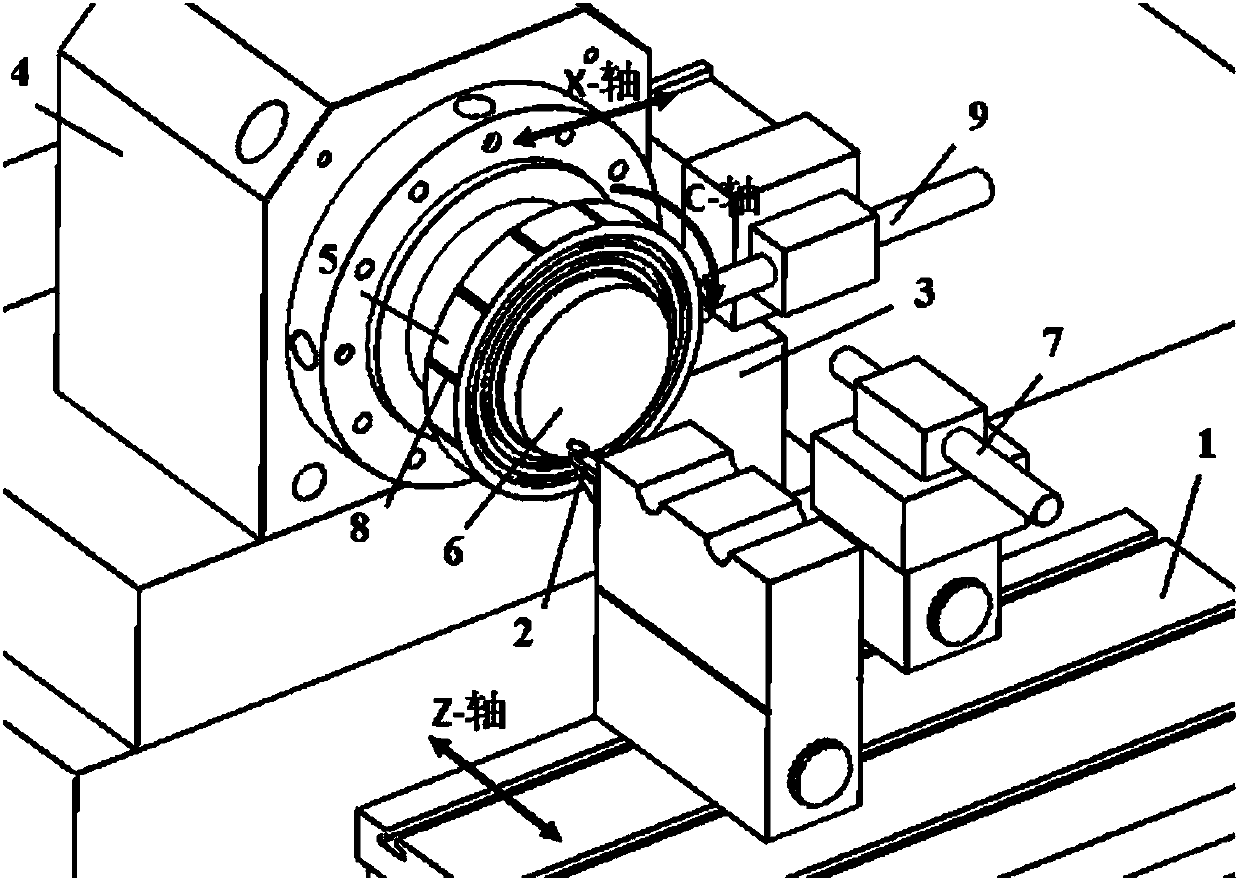
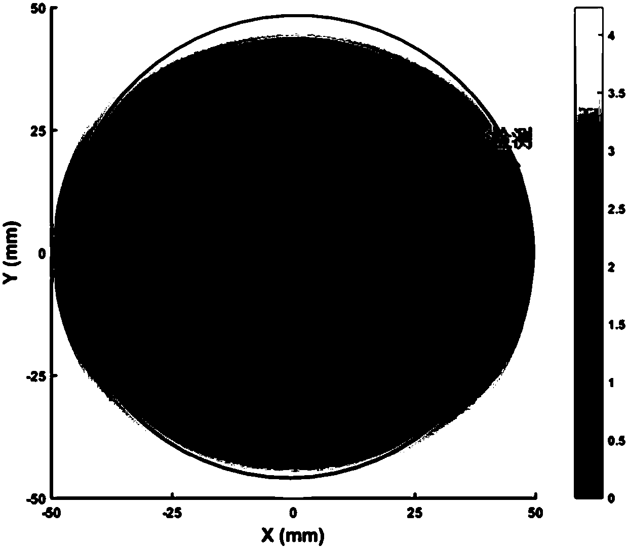
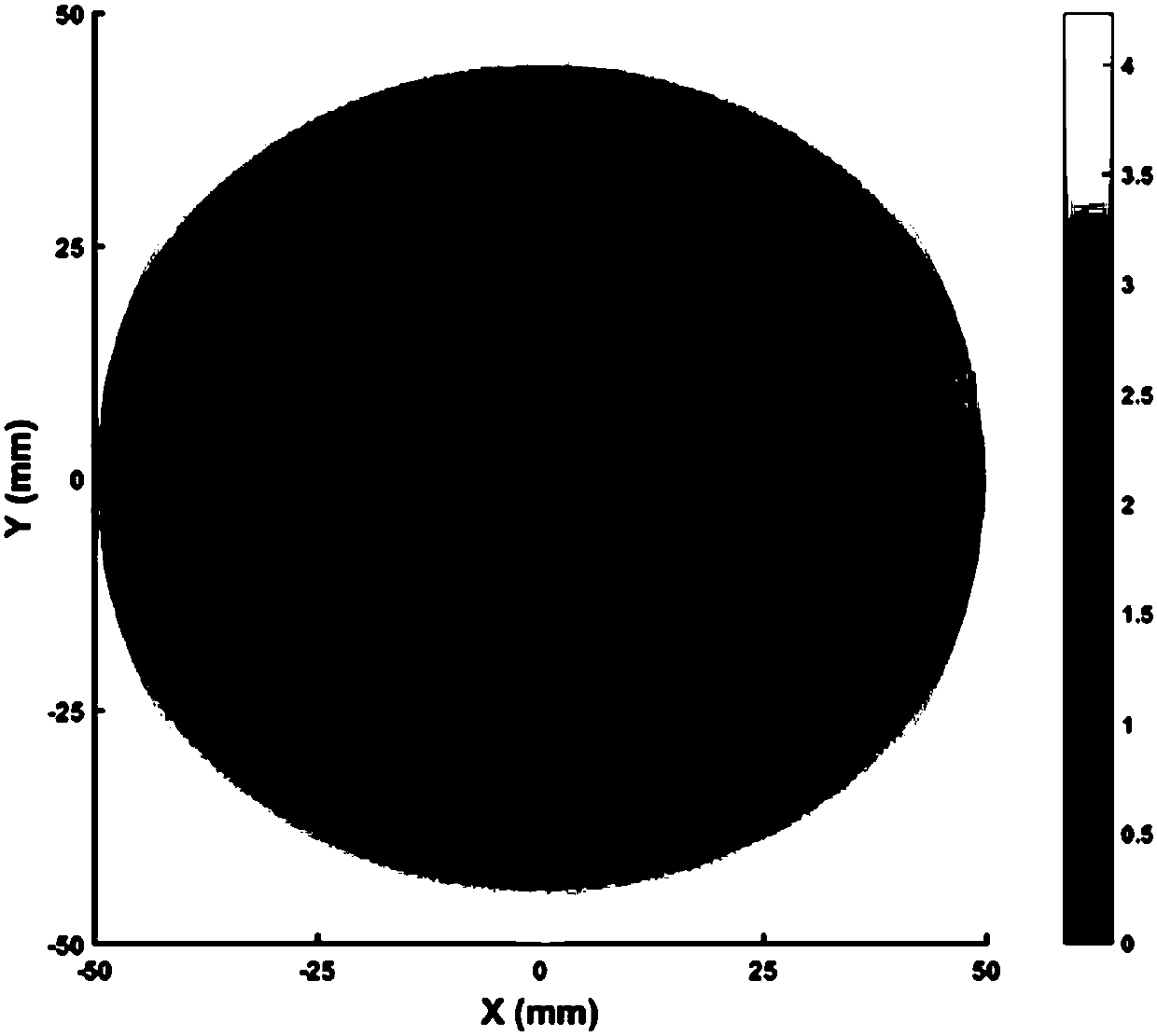
[0060] In this embodiment, an off-axis parabolic mirror with a diameter of 100 mm is taken as an example to further illustrate the above solution. This embodiment adopts the structure of the device such as figure 1 As shown, the tool platform 1 moves along the Z axis, the processing tool 2 is a single-point diamond tool, the spindle platform 3 moves along the X axis, and the lathe spindle 4 is the air bearing spindle of the precision turning lathe. The material of the off-axis parabolic mirror to be processed is 6061 aluminum alloy, the radius of curvature of the apex is 256.174mm, the off-axis distance is 147.902mm, the machining aperture is 100mm, and the inclination angle is 30°. The measuring ranges of the first optical probe 7 and the second optical probe 9 used in this embodiment are both 300 μm. By adopting the above method, the non-rotationally symmetrical free-form surface with large diameter is machined by slow tool servo, and the surface shape error of the processe...


PUM

PropertyMeasurementUnit
Caliber sizeaaaaaaaaaa

Abstract

The invention relates to a free-form surface machining method and device based on a two-step online detection and compensation technology. The method comprises the steps that a machined workpiece is initially machined according to a design path, and a designed free-form surface is obtained; the surface-shaped error and rotation direction angle of the designed free-form surface are detected synchronously; the design path is amended on the basis of the surface-shaped error and rotation direction angle, and a primary amended machining path is obtained; the designed free-form surface is subjectedto primary compensation machining on the basis of the primary amended machining path, and a primary compensation free-form surface is obtained; radial detection through a center point is conducted onthe primary compensation free-form surface; the primary amended machining path is amended on the basis of the radial detection data, and a secondary amended machining path is obtained; and the primarycompensation free-form surface is subjected to secondary compensation machining on the basis of the secondary amended machining path. Compared with the prior art, the free-form surface machining method and device based on the two-step online detection and compensation technology have the advantages of being high in detection precision, high in compensation precision and the like.

Description

technical field [0001] The invention belongs to the field of ultra-precision turning processing, and in particular relates to a free-form surface processing method and device based on two-step on-line detection and compensation technology. Background technique [0002] Freeform surfaces are widely used in imaging and non-imaging systems, which can effectively shorten the total length of the optical system and improve imaging quality. Freeform surfaces provide designers with more degrees of freedom in design, so in recent years, they have made great progress in the fields of aerospace, lighting, and bioengineering. However, due to the non-rotational symmetry of the free-form surface, the high-precision machining of its surface shape has always been an important and difficult research point at home and abroad. [0003] Ultra-precision turning technology adopts single-point diamond turning tools to directly process lenses with an optical surface roughness. It is often used to ...

Claims


Application Information

Patent Timeline
IPC IPC(8): B23B25/06
Inventor 王占山沈正祥余俊王晓强
Owner TONGJI UNIV
Learn More