
Eureka
For R&D, Eureka makes reading and utilizing patents & technical documents easy.
Eureka AIR
Designed for self-driven R&D workflows. Generate viable solutions, solve complex R&D challenges, empower your innovation with AI.

Eureka Materials
Designed for material experts only. Revolutionize your material R&D, from search, analyze, to developing new materials.

TechResearch
Generate reliable direction feasibility study reports for your R&D in just a few steps.

TechSeek
Discover and master advanced knowledge NOW. Basics, ideas, possibilities, all at once.

TechMind
As an expert in R&D Theories, TechMind can generates customized viable solutions instantly.

TechRisk
Analyze your overall solution with one click, know your potential R&D risks in advance.

TechMonitor
Get weekly tech updates, stay abreast of the latest tech innovations and key insights.
Self-expansion type woven stent and conveying device thereof
A delivery device and self-expanding technology, applied in the field of medical devices, can solve the problems of axial shortening, stent flexibility and resistance to bending and kinking, and the release position is not ideal.
- Summary
- Abstract
- Description
- Claims
- Application Information
AI Technical Summary
Problems solved by technology
Method used
Image

Examples
Embodiment 1
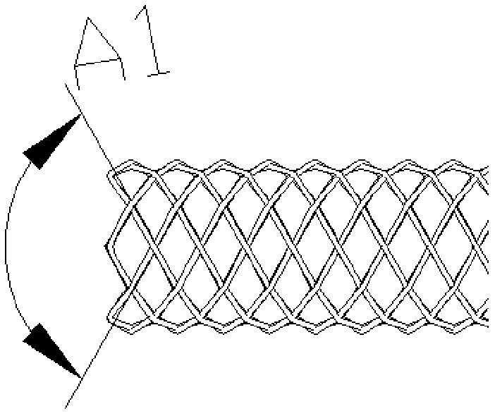
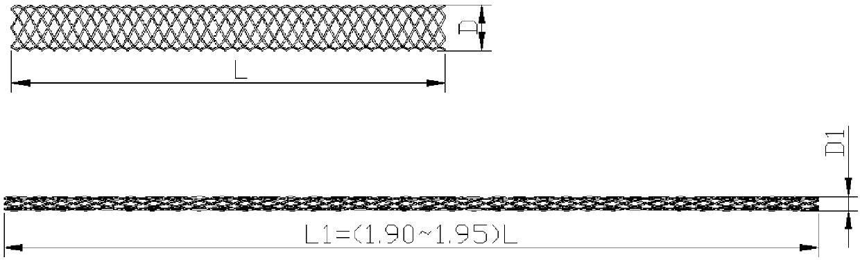
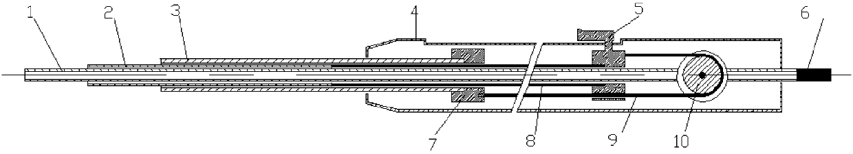
[0096] In this embodiment, the stent is braided with 0.15mm nickel-titanium wire, the diameter is 4.5mm, the number of stent braiding heads is 4, the braiding angle A1 is 120°, the stent is loaded and compressed in the stent restraint tube, and the stent released from the stent restraint tube The axial shortening rate was 47.6%, and the inner diameter of the stent-binding tube was about 1.75mm. In this embodiment, a fixed pulley transmission device is used to control the bracket binding tube 3 and the bracket pushing tube 2 to move toward each other. The transmission device is composed of a conveyor belt 9 and a fixed pulley 10. One end of the conveyor belt and the outer surface of the bracket restraining pipe 3 are connected through a bracket restraining pipe joint 7, and the bracket restraining pipe joint 7 is fixed on the proximal outer surface of the bracket restraining tube 3, and the bracket pushes the pipe The proximal end of 2 is connected with a drive device 8, and th...
Embodiment 2
[0098] In this embodiment, the stent is braided with 0.18mm nickel-titanium wire, the diameter is 7.0mm, the number of stent braiding heads is 6, the braiding angle A1 is 118.5°, the stent is loaded and compressed in the stent restraint tube, and the stent released from the stent restraint tube The axial shortening rate was 46.6%, and the inner diameter of the stent-binding tube was about 1.9mm. In this embodiment, a rack-and-pinion transmission device is used to control the bracket binding tube 3 and the bracket pushing tube 2 to move toward each other. The transmission device is composed of two oppositely moving racks S1, S2 and gear S3, wherein the rack S2 is connected to the bracket restraining tube through the conveyor belt and the bracket restraining pipe joint, and the rack S1 is connected to the bracket pushing tube through a rigid push tube. By loading the rotary handle on the gear S3, the gear S3 is driven to rotate clockwise, and then the racks S1 and S2 are driven ...
Embodiment 3
[0100] In this embodiment, the stent is braided with 0.15mm nickel-titanium wire, the diameter is 6.0mm, the number of stent braiding heads is 6, the braiding angle A1 is 119°, the stent is loaded and compressed in the stent restraint tube, and the stent released from the stent restraint tube The axial shortening rate was 46.9%, and the inner diameter of the stent-binding tube was about 1.65mm. In this embodiment, the rack-and-pinion transmission device same as that in Embodiment 2 is used to control the bracket binding tube 3 and the bracket pushing tube 2 to move toward each other. The difference is that the preoperative detachable gun handle is used to drive the gear S3 to rotate clockwise.
[0101] The specific process is: the support restraining tube 3 is connected with the rigid connector 11 of the handle through the buckle 15, and when the rigid connector 11 moves to the far end (right end), it drives the support restraining tube 3 to move to the far end; and the suppor...
PUM
| Property | Measurement | Unit |
|---|---|---|
| Braiding angle | aaaaa | aaaaa |
| Outer diameter | aaaaa | aaaaa |
| Wire diameter | aaaaa | aaaaa |
Abstract
Description
Claims
Application Information
 - R&D Engineer
- R&D Manager
- IP Professional
- Industry Leading Data Capabilities
- Powerful AI technology
- Patent DNA Extraction
Browse by: Latest US Patents, China's latest patents, Technical Efficacy Thesaurus, Application Domain, Technology Topic, Popular Technical Reports.
© 2024 PatSnap. All rights reserved.Legal|Privacy policy|Modern Slavery Act Transparency Statement|Sitemap|About US| Contact US: help@patsnap.com