Check patentability & draft patents in minutes with Patsnap Eureka AI!

Confocal auto-collimation decentration and curvature radius measurement method and device

A technology of curvature radius and measurement method, which is applied in the direction of measuring device, optical device, geometric characteristics/aberration measurement, etc., can solve the problems of inability to accurately locate the lens, poor axial positioning accuracy, and inability to tomographically locate, etc., to achieve The effect of improving measurement efficiency, reducing volume, and simplifying the measurement process

Active Publication Date: 2018-03-27
BEIJING INSTITUTE OF TECHNOLOGYGY
View PDF9 Cites 17 Cited by
  • Summary
  • Abstract
  • Description
  • Claims
  • Application Information

AI Technical Summary

Problems solved by technology

[0007] 1) Before the measurement center, other methods are needed to measure the radius of curvature of the lens, and repeated clamping will introduce measurement errors;
[0008] 2) The axial positioning accuracy is poor, and it cannot be accurately positioned at the center of the lens, and the presence of centering offset will introduce measurement errors;
[0009] 3) Tomographic positioning is not possible. When measuring the center deviation of the lens group, to locate the spherical center of the next lens, it is necessary to obtain the optical parameters of all previous lenses in advance. The calculation is complicated, and the positioning position is the theoretical position, so the positioning is not accurate

Method used


Image

  • Confocal auto-collimation decentration and curvature radius measurement method and device
  • Confocal auto-collimation decentration and curvature radius measurement method and device
  • Confocal auto-collimation decentration and curvature radius measurement method and device

Examples


Embodiment 1

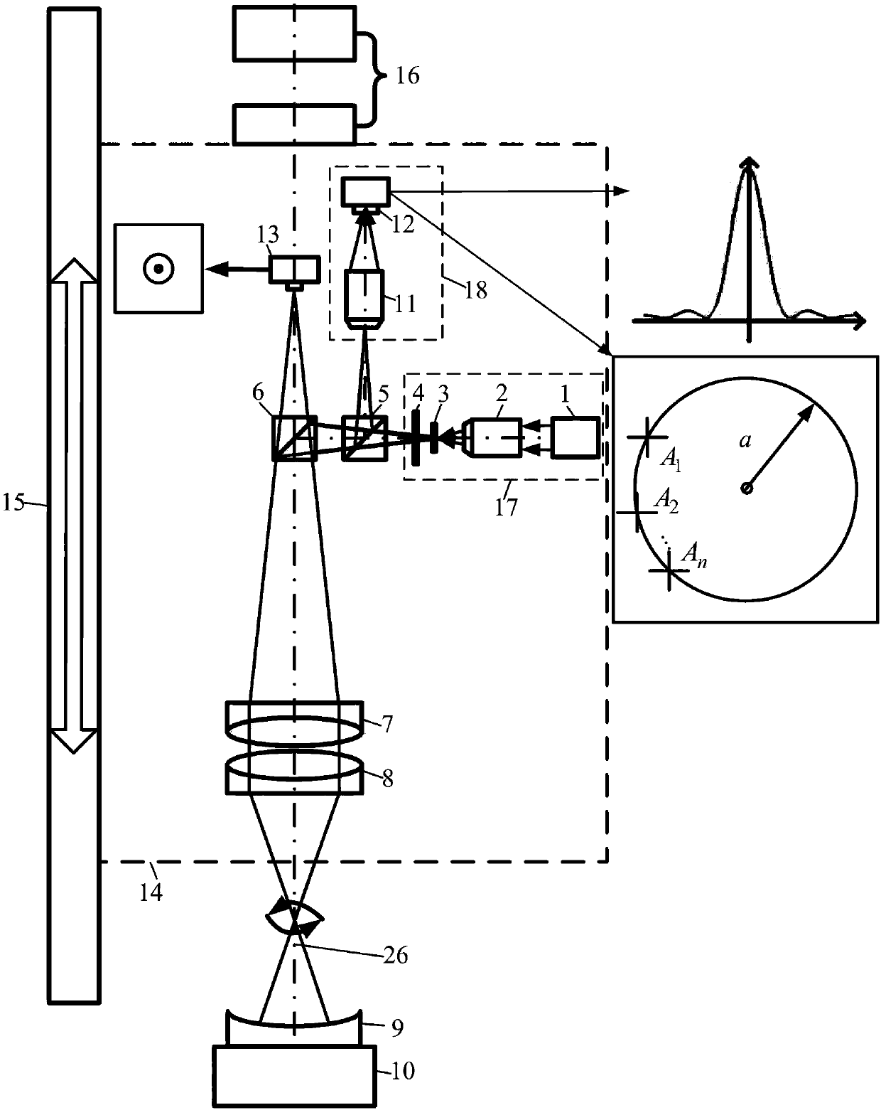
[0045] Such as figure 1 , figure 2 and image 3 As shown, the confocal autocollimation center deviation and curvature radius measurement method, the measurement steps are:

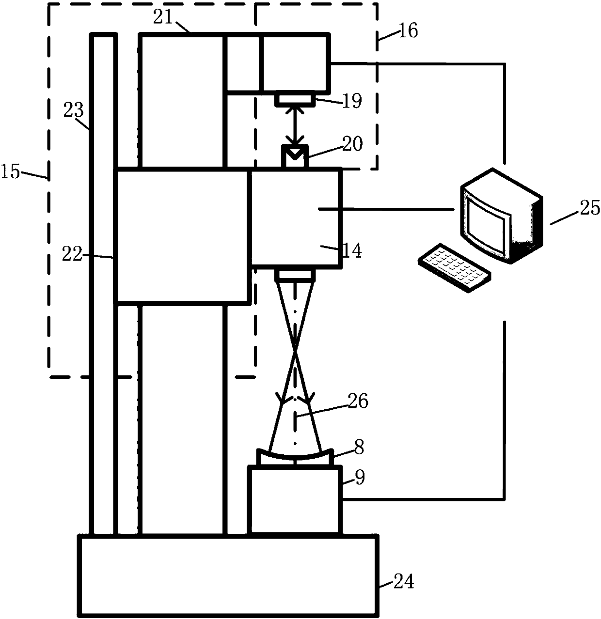
[0046] Before the measurement, first adjust the measuring optical axis 26 to coincide with the axis of the air bearing rotating shaft 10, the measuring optical axis 26 to be parallel to the air bearing guide rail 21, and the optical axis of the length measuring interferometer 19 to coincide with the measuring optical axis 26. During detection, place a flat mirror as the measured mirror 9 at the center of the air-floating shaft 10, start the driving screw 23 to drive the slider 22 to focus the measuring light cone emitted by the measuring host 14 on the surface of the flat mirror; start the air-floating shaft 10 to drive the flat mirror Rotate, observe the paths of the light spots on the first detector 13 and the confocal detector 18, and adjust the axial plane of the air bearing shaft 10, so that the li...

Embodiment 2

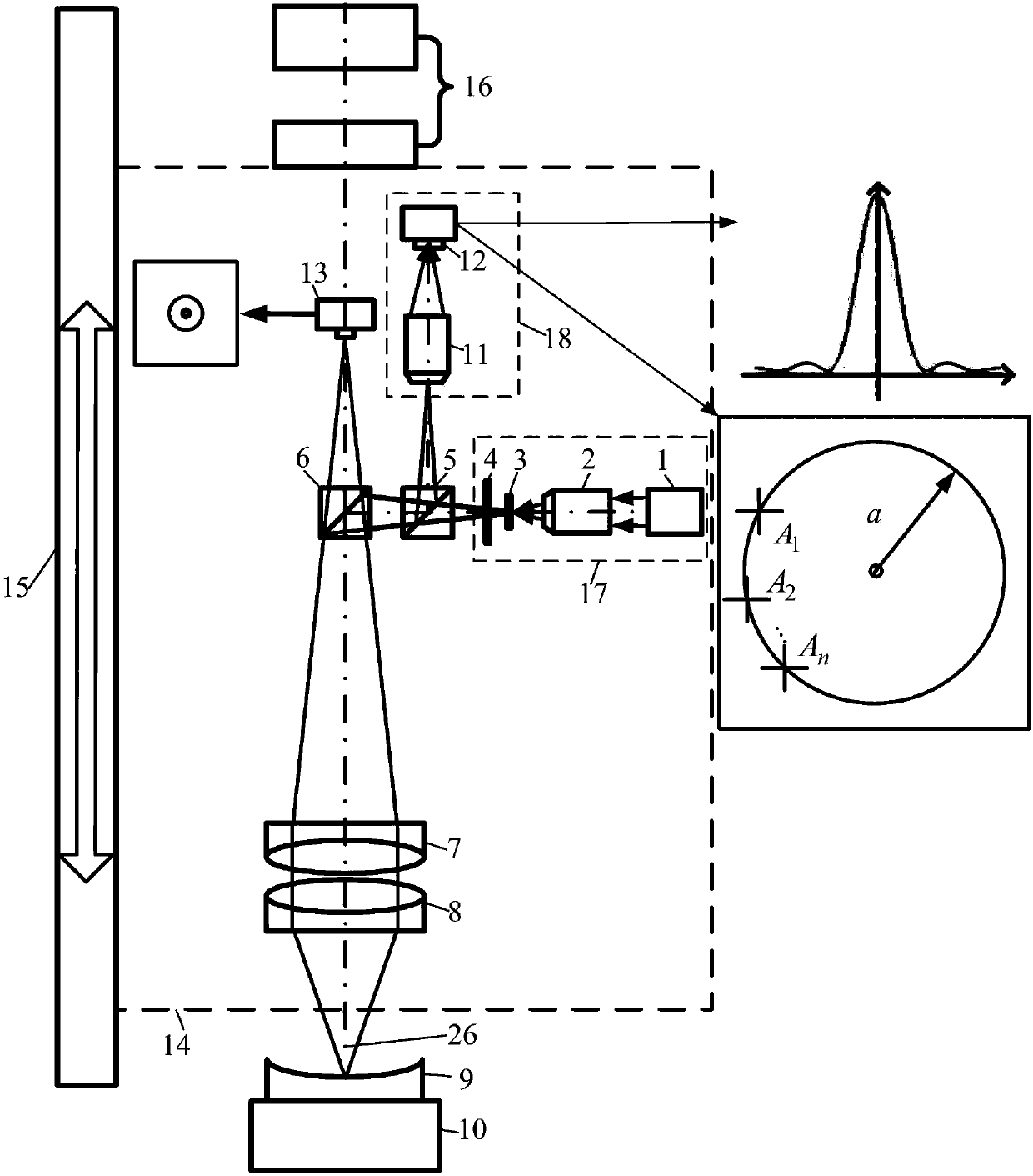
[0055] Such as Figure 4 As shown, the confocal autocollimation center deviation and radius of curvature measurement method can also measure the curvature radius and center deviation of the convex lens, and the measurement steps are the same as in embodiment 1:

[0056] First, the axis of the air-floating rotating shaft 10 is adjusted to coincide with the optical axis 26 of the measuring host 14. The measured mirror 9 is a convex lens placed at the center of the air-floating rotating shaft 10, and the measuring host 14 is moved along the direction of the measuring optical axis 26 to make the measuring light cone Focus on the vertex and the center of the sphere of the mirror under test 9 respectively, and the length measurement interferometer 19 records the vertex z 1 and center z 2 , the calculated radius of curvature r=z 1 -z 2 ; at center z 2 At the position, the air-floating rotating shaft 10 is started to drive the measured mirror 9 to rotate, the radius of the fitting...

Embodiment 3

[0058] Such as Figure 5 As shown, the confocal autocollimation center deviation and curvature radius measurement method can also measure the curvature radius and center deviation of the lens group, and obtain the best fitting optical axis. The measurement steps are:

[0059] Step 1. The lens group is used as the measured mirror 9, placed in the center of the air-floating shaft 10, the bottom surface coincides with the axial surface of the air-floating shaft 10, the screw 23 drives the slider 22 to move along the guide rail 21, so that the measuring light cone is focused on the first The spherical center of a lens, detect the eccentricity of the first lens χ 1 =a 1 / (2β);

[0060] Step 2, move the measuring host 14, focus the measuring light cone to the center of the second lens, detect the eccentricity between the second lens and the axis of the lens group, and take into account the eccentricity and spacing introduced by the first lens during calculation Magnification to c...


PUM


Abstract

The invention belongs to the technical field of optical precision processing and detection, and relates to a confocal auto-collimation decentration and curvature radius measurement method and device.The method uses a confocal chromatographic focusing method to focus the sphere center and the vertex of a detected mirror, measures the position of the focusing point with the help of a position detection system, calculates and obtains the curvature radius of the detected mirror, uses an auto-collimation method to detect the path of reflection light on a detection surface during the rotating process of the detected mirror to acquire the eccentricity of the detected mirror and integrates the eccentricity and the curvature radius to obtain the decentration. The confocal chromatographic focusingprinciple is firstly applied to the decentration measurement field, the traditional auto-collimation decentration measurement method is improved, the confocal auto-collimation decentration and curvature radius measurement device is also provided, the measurement result shows that the method has the advantages of high measurement precision, large range, high efficiency and no repeated assembling and clamping, and can be used in precision processing and detection on the decentration and the curvature radius of an optical element.

Description

technical field [0001] The invention belongs to the technical field of optical precision machining and detection. It combines confocal tomographic fixed-focus technology and self-collimation center deviation measurement technology, and relates to a confocal self-collimation center deviation and curvature radius measurement method and device, which can be used for spherical lenses and The measurement of center deviation and radius of curvature of the spherical mirror and the detection of center deviation of the lens group and the best optical axis fitting. technical background [0002] The center deviation of optical components is one of the manufacturing errors of optical instruments, which has a great influence on the quality of the optical assembly of the whole machine, and is also difficult to control. The existence of center deviation destroys the coaxiality of the optical system, resulting in astigmatism and asymmetry of distortion. Therefore, it is of great significan...

Claims


Application Information

Patent Timeline
IPC IPC(8): G01B11/27G01B11/255G01M11/02
CPCG01B11/255G01B11/27G01M11/0242
Inventor 赵维谦葛洪邱丽荣
Owner BEIJING INSTITUTE OF TECHNOLOGYGY
Features
  • R&D
  • Intellectual Property
  • Life Sciences
  • Materials
  • Tech Scout
  • Unparalleled Data Quality
  • Higher Quality Content
  • 60% Fewer Hallucinations
Learn More