Biogas digester

The technology of a biogas digester and a gas storage chamber is applied in the field of biogas digesters, which can solve the problems of low gas production rate, low utilization rate of fermentation raw materials, influence on the gas production volume of the digester, etc., and achieve the effect of increasing the gas production volume.

Inactive Publication Date: 2018-04-03
CHENGDU JINHUI TECH
View PDF1 Cites 2 Cited by
  • Summary
  • Abstract
  • Description
  • Claims
  • Application Information

AI Technical Summary

Problems solved by technology

Although hydraulic biogas digesters have the above advantages, there are also many disadvantages: First, due to repeated changes in air pressure, this has a negative impact on the strength of the pool body and the stability and improvement of the combustion efficiency of lamps and stoves.
But this patent document is because there is no stirring device in the pool, and the scum in the pool is easy to crust and is difficult to break, so the utilization rate of fermentation raw materials is not high, and the gas production rate is very low. The side walls of the pressure chamber are connected, and the discharge port is exposed to the air, so the ammonium nitrogen in the biogas is very volatile, which is not conducive to maintaining the temperature of the biogas digester, and further affects the gas production of the biogas digester.

Method used


Image

  • Biogas digester
  • Biogas digester

Examples


Embodiment 1

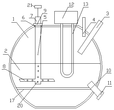
[0025] See figure 1 , A biogas digester, comprising a gas storage chamber 1 and a fermentation chamber 2, a feed pipe 3 and a gas outlet pipe 4 communicating with the gas storage chamber 1, and also includes a stirrer 5. The outer wall of the gas storage chamber 1 is provided with an annular hole 6 for stirring The stirring shaft 7 of the device 5 extends into the fermentation chamber 2 through the annular hole 6, a stirring blade 8 located in the fermentation chamber 2 is provided on the stirring shaft 7, and a stirring shaft 7 located outside the gas storage chamber 1 A card cover 9 is sleeved, the diameter of the card cover 9 is not less than the inner diameter of the annular hole 6, a discharging tube 10 is arranged in the fermentation chamber 2, and a discharging cover 11 is arranged at the outlet of the discharging tube 10, the A solar heat collector 12 is fixedly connected to the top of the gas storage chamber 1, and a heat collection return pipe 13 is connected to the so...

Embodiment 2

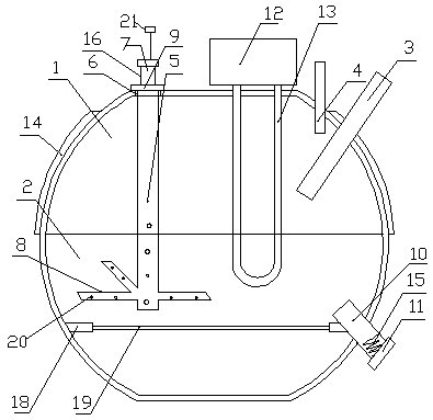
[0028] See figure 2 , A biogas digester, comprising a gas storage chamber 1 and a fermentation chamber 2, a feed pipe 3 and a gas outlet pipe 4 communicating with the gas storage chamber 1, and also includes a stirrer 5. The outer wall of the gas storage chamber 1 is provided with an annular hole 6 for stirring The stirring shaft 7 of the device 5 extends into the fermentation chamber 2 through the annular hole 6, a stirring blade 8 located in the fermentation chamber 2 is provided on the stirring shaft 7, and a stirring shaft 7 located outside the gas storage chamber 1 A card cover 9 is sleeved, the diameter of the card cover 9 is not less than the inner diameter of the annular hole 6, a discharging tube 10 is arranged in the fermentation chamber 2, and a discharging cover 11 is arranged at the outlet of the discharging tube 10, the A solar heat collector 12 is fixedly connected to the top of the gas storage chamber 1, and a heat collection return pipe 13 is connected to the ...


PUM


Abstract

The invention discloses a methane digester, which comprises a gas storage chamber and a fermentation chamber, a feed pipe and an air outlet pipe communicated with the gas storage chamber, and a stirrer, an annular hole is opened on the outer wall of the gas storage chamber, and the stirring shaft of the stirrer passes through the Extending into the fermentation chamber, the stirring shaft is provided with a stirring blade located in the fermentation chamber, a card cover is set on the stirring shaft located outside the air storage chamber, a discharge pipe is arranged in the fermentation chamber, and the top of the air storage chamber is fixedly connected with The solar heat collector is connected with a heat collecting return pipe, the fermentation chamber is fixedly connected with a compartment plate, the stirring shaft is a hollow stirring shaft, the stirring blade is a hollow stirring blade, and the hollow stirring shaft and the hollow stirring blade are All have defoaming holes, and a vacuum defoamer is connected to the top of the stirring shaft. By installing solar heat collectors, a good temperature in the fermentation room can be maintained, and the use of partition boards can fully ferment the fermentation materials, thereby greatly increasing the gas production of the biogas digester.

Description

Technical field [0001] The invention relates to the technical field of biogas, in particular to a biogas digester. Background technique [0002] Biogas is a mixture of various gases, the main component of which is methane. People often say that biogas fermentation refers to the process by which biogas bacteria decompose organic matter to produce biogas. According to the role of various bacteria in the biogas fermentation process, biogas bacteria can be divided into two categories. The first type of bacteria is called decomposing bacteria, and its function is to decompose complex organic matter into simple organic matter and carbon dioxide. Among them, there are cellulolytic bacteria that specifically decompose cellulose; protein-decomposing bacteria that specifically decompose protein; lipolytic bacteria that specifically decompose fat; the second type of bacteria is called methanogenic bacteria, usually called methanogenic bacteria. Its function is to oxidize or reduce simpl...

Claims


Application Information

Patent Timeline
IPC IPC(8): C12M1/21C12M1/12C12M1/107C12M1/02
CPCC12M21/04C12M23/34C12M23/36C12M23/38C12M27/02C12M41/02C12M41/24C12M43/00
Inventor 张一帆
Owner CHENGDU JINHUI TECH
Why Eureka
Try Eureka