
Condensation type fuel gas heating stove

A gas heating and condensing technology, used in air heaters, lighting and heating equipment, fluid heaters, etc., can solve problems such as maintaining constant value, energy waste, and efficiency drop, reducing excess air coefficient and increasing dew point temperature. , the effect of increasing the condensation effect

Inactive Publication Date: 2018-04-03
QINGDAO ECONOMIC & TECHN DEV ZONE HAIER WATER HEATER
View PDF5 Cites 5 Cited by
  • Summary
  • Abstract
  • Description
  • Claims
  • Application Information

AI Technical Summary

Problems solved by technology

[0004] The technical problem to be solved by the present invention is to overcome the deficiencies of the prior art, and to provide an atmosphere-balanced condensing gas-fired heating furnace that combines a non-inductive brushless DC fan and a waste heat recovery device to form a core energy-saving component. The DC fan has an adjustable wind speed and is Closed-loop feedback can realize the high efficiency of the heating furnace at different power levels, and keep the air-fuel ratio at a constant value, thus completely solving the problem that the efficiency of the heating furnace decreases with the power reduction caused by the fixed wind speed of the AC fan or the narrow adjustment range. Energy waste; on the other hand, by controlling the air volume of the DC fan to increase the condensation effect of the waste heat recovery device on water vapor below the rated power, so that the condensation effect is better and energy is saved; in addition, the fan The electric control board is separated from the fan body and there is no induction element in the fan body. The fan body can adapt to harsh environments, so that the heating furnace can be widely used in various environments

Method used


Image

  • Condensation type fuel gas heating stove

Examples


Embodiment 1

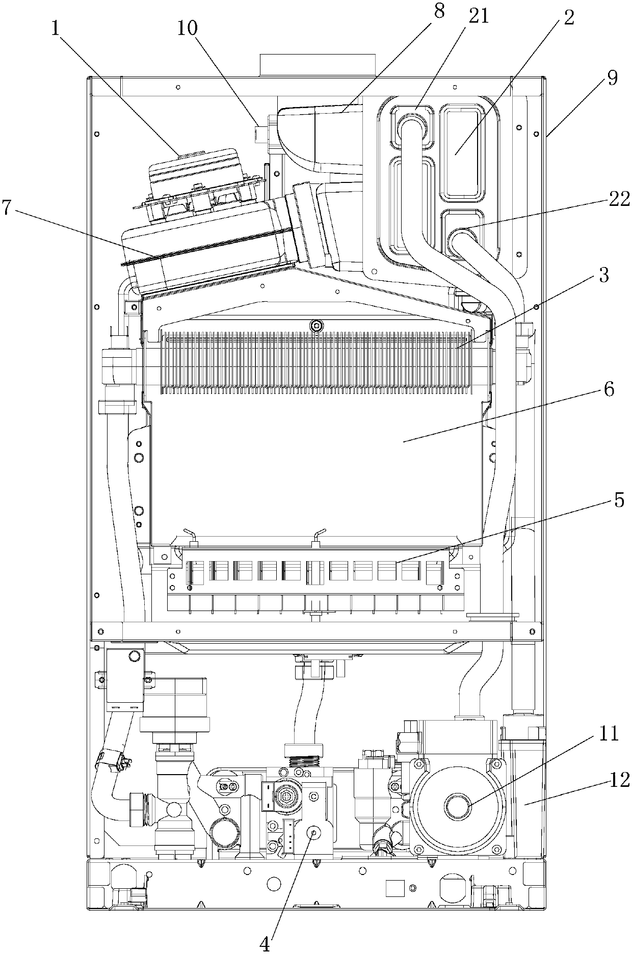
[0032] like figure 1Shown is a structural schematic diagram of a condensing heating furnace. The gas condensing dual-purpose heating furnace described in this embodiment, which can precisely control the air volume and increase the condensation effect, is an "IP" type gas heating and hot water equipment, which can provide two water supplies for domestic water and heating water. One road is for domestic water supply, which directly uses the combustion heat of combustible energy to heat water, and then provides the heated hot water to users, which is mainly used in daily life; the other road is for heating water, which is used to increase the temperature of the heating space. The heating water channel in the heating furnace is connected to the water channel in the heating space: the heating furnace heats the heat exchange medium (here is liquid water), and then the heated high-temperature heat exchange medium communicates with the external medium through the medium such as the pi...

Embodiment 2

[0040] This embodiment is a further limitation of the first embodiment above. The waste heat recovery device 2 is provided with a water inlet 21 and a water outlet 22 . The water inlet 21 is connected to the circulating water pump 11 , and the water outlet 22 is connected to the main heat exchanger 3 . And the level of the water outlet 22 is lower than that of the water inlet 21 to facilitate the liquid to flow out. The liquid inside the system (i.e. heat exchange medium) first enters the waste heat recovery device 2 through the water inlet 21 through the circulating water pump 11, and enters the main heat exchanger 3 through the water outlet 22 after exchanging heat with low-temperature flue gas in the waste heat recovery device 2. One end of the main heat exchanger 3 is connected to the water outlet 22 of the waste heat recovery device 2, and the other end is connected to the hot water outlet. The liquid inside the system exchanges heat with the high-temperature flue gas in ...

Embodiment 3

[0042] This embodiment is a further limitation of the above-mentioned first embodiment: the electric control board of the DC fan is separated from the fan body 1, and the electric control board can work normally after being installed in an area where the temperature limit of the electric control board components is allowable. Compared with the fan electric control board, the fan body 1 can adapt to a wider temperature range, and after eliminating the influence of the environmental adaptability of the fan electric control board, the heating furnace of the DC fan can be applied to work in harsh environments. Preferably, the fan electric control board of the DC fan is integrated with the overall electric control board of the heating furnace, and the centralized design of the electric control board makes the external control operation more convenient and simple.

[0043] Preferably, there is no induction element in the fan body 1. During the working process of the heating furnace, ...


PUM


Abstract

The invention discloses a condensation type fuel gas heating stove. The condensation type fuel gas heating stove comprises a main heat exchanger, a gas valve, a combustor, a combustion cavity, a smokecollecting hood, a flue, a shell and a circulating water pump and further comprises a direct-current draught fan and a waste heat recycling device; the direct-current draught fan is a noninductive brushless direct-current draught fan and comprises a draught fan electric control plate and a draught fan body, the draught fan body is separated from the draught fan electric control plate, and is mounted between the main heat exchanger and the waste heat recycling device, the draught fan electric control plate adjusts the rotating speed of the draught fan body in real time along with changes of combustion power of the heating stove, and controls the air-fuel ratio in the combustion process to be kept unchangeable, the noninductive brushless direct-current draught fan is adopted in the heatingstove, no induction elements exist in the draught fan body, the draught fan body and the draught fan electric control plate are separated, and the draught fan body can be applied to the severe environment; meanwhile, the wind speed of the direct-current draught fan is precisely adjustable, the air-fuel ratio in the combustion cavity is kept as definite value under different types of combustion power, meanwhile, the heating stove is combined with the waste heat recycling device to promote the condensation effect, work efficiency is improved, and energy is saved.

Description

technical field [0001] The invention relates to the technical field of fluid heaters, in particular to a gas heating furnace, in particular to a condensing gas heating furnace which can improve the condensation effect. Background technique [0002] Some premixed "IP type" gas heating water heaters currently on the market basically use AC fans as the delivery unit for the air volume used for combustion. At the same time, the AC fan is also combined with the waste heat recovery module to promote the condensation effect of the waste heat recovery module. However, when the AC fan is used as a heating furnace fan, its speed is fixed or the adjustment range is narrow. When the heating furnace burns at different power levels, the air volume delivered by it will lead to inconsistent thermal efficiency of the heating furnace when burning at different power levels, which cannot be guaranteed. The air-fuel ratio is always kept at the optimal ratio state, and as the power decreases, the...

Claims


Application Information

Patent Timeline
IPC IPC(8): F24H8/00F24H9/18
CPCF24H8/006F24H9/1836Y02B30/00
Inventor 孟令建郑涛曹立国靳德峰刘学
Owner QINGDAO ECONOMIC & TECHN DEV ZONE HAIER WATER HEATER
Learn More