Efficient dewatering device for natural gas

A dehydration device, natural gas technology, applied in the direction of combined devices, gas fuel, petroleum industry, etc., can solve the problems of low dehydration efficiency, low efficiency, and various equipment in the dehydration tower, so as to improve efficiency and quality, save time, and improve production efficiency Effect

Active Publication Date: 2018-04-06
四川科比科油气工程有限公司
View PDF9 Cites 1 Cited by
  • Summary
  • Abstract
  • Description
  • Claims
  • Application Information

AI Technical Summary

Problems solved by technology

[0003] The technical problem to be solved by the present invention is that cooling natural gas is usually used for dehydration, that is, the natural gas is passed through the bottom of the dehydration tower, and then the cold air is passed through the top of the dehydration tower, and then the cold air and the natural gas are in convective contact to make the water in it Removal after condensation, but the dehydration efficiency of the existing dehydration tower is low, and usually requires multiple dehydration processes to completely remove the water, which is low in efficiency, requires a lot of equipment, and is costly. The purpose is to provide efficient dehydration for natural gas. The device first divides the flow of natural gas and cold air, and at the same time increases the contact area between cold air and natural gas during convection, greatly improving the water removal efficiency, making the water removal in natural gas after a dehydration process more thorough, and improving Improve production efficiency, save the time of multiple cycle dehydration process, make water can be completely removed at one time, no need for multiple equipment for continuous dehydration, saving cost

Method used


Image

  • Efficient dewatering device for natural gas
  • Efficient dewatering device for natural gas

Examples


Embodiment

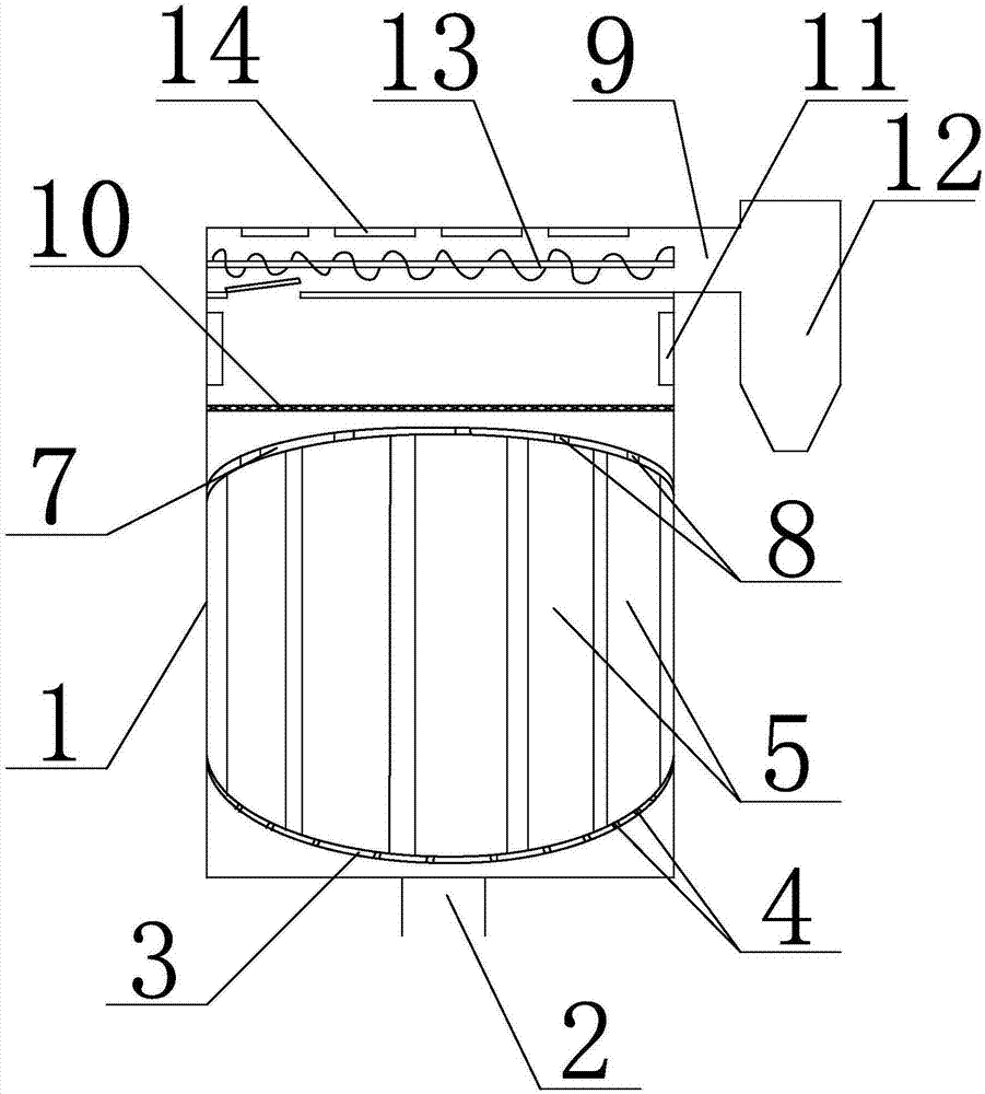
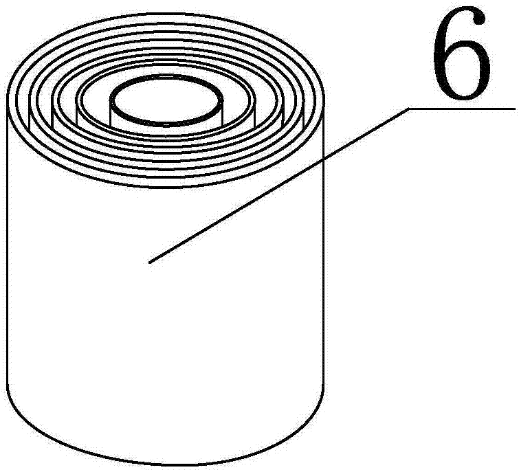
[0022] Such as figure 1 with figure 2 As shown, the high-efficiency dehydration device for natural gas of the present invention includes a dehydration tower 1, a natural gas inlet 2 is provided at the bottom of the dehydration tower 1, a spherical arc plate 3 is provided above the air inlet 2 in the dehydration tower 1, and the spherical arc The edge of the plate 3 is fully attached to the inner wall of the dehydration tower 1 and the opening faces upwards. The spherical arc plate 3 is evenly provided with a plurality of ventilation holes 4, and the spherical arc plate 3 is connected with a plurality of dehydration pipes 5. The ventilation holes 4 and the dehydration pipes The lower end of 5 is connected, and the dehydration pipe 5 is provided with a shunt sleeve 6. The shunt sleeve 6 is formed by multiple sleeves with different sizes from the inside to the outside. The shunt sleeve 6 can rotate around its own axis. , and the sleeves are all mesh-like hollow structures, fill...


PUM


Abstract

The invention discloses an efficient dewatering device for natural gas. The efficient dewatering device comprises a dewatering tower, wherein a natural gas inlet is formed in the bottom of the dewatering tower, a spherical arched plate is arranged, above the gas inlet, in the dehydrating tower, a plurality of ventilating holes are uniformly formed in the spherical arched plate, the spherical arched plate is connected with a plurality of dewatering pipes, a flow diversion sleeve is arranged in each dewatering pipe, a cold air flow distribution plate is arranged above the dewatering pipes, a plurality of cold air through holes are uniformly formed in the cold air flow distribution plate, a cold air inlet is arranged above the cold air flow distribution plate, and a gas outlet is formed in the side wall of the top of dehydrating tower and is connected with a cyclone separator. According to the dewatering device disclosed by the invention, through carrying out flow diversion on natural gasand cold air, the area of contact between the cold air and the natural gas during convection is increased, the removal efficiency of water is greatly increased, thus, the removal of water from natural gas subjected to one-time dewatering process is more thorough, the production efficiency is increased, the time of repeated cycled dewatering process is saved, and the cost is reduced.

Description

technical field [0001] The invention relates to a dehydration device, in particular to a high-efficiency dehydration device for natural gas. Background technique [0002] Natural gas refers to all gases that exist naturally in nature, including gases formed by various natural processes in the atmosphere, hydrosphere, and lithosphere (including oil field gas, gas field gas, mud volcano gas, coal bed methane, and biologically generated gas, etc.). The definition of "natural gas" that people have used for a long time is a narrow definition from the perspective of energy, which refers to the mixture of hydrocarbon and non-hydrocarbon gases naturally stored in the formation. In petroleum geology, it usually refers to oil field gas and gas field gas. Its composition is dominated by hydrocarbons and contains non-hydrocarbon gases. Natural gas is stored in underground porous rock formations, including oil field gas, gas field gas, coal bed methane, mud volcano gas and biologically...

Claims


Application Information

Patent Timeline
Patent Type & Authority Applications(China)
IPC IPC(8): B01D50/00C10L3/10
CPCC10L3/106B01D50/40
Inventor 刘敏陈志国朱江
Owner 四川科比科油气工程有限公司
Why Eureka
Try Eureka