Automatic transferring, loading and unloading device for high-temperature molds, high-efficiency machining system for 3D cover glass and machining method of system

A molding die, high temperature molding technology, applied in glass molding, glass remolding, glass manufacturing equipment and other directions, can solve the problems of poor thermal uniformity of cover glass, maximum heating temperature limit, poor thermal uniformity of forming molds, etc. Achieve the effect of improving processing efficiency, avoiding temperature loss and reducing contact area

Pending Publication Date: 2018-04-06
苏州赛万玉山智能科技有限公司
0 Cites 8 Cited by

AI-Extracted Technical Summary

Problems solved by technology

[0008] The resistance rod heating forming process is to heat the forming mold through the resistance heating tube and indirectly heat the forming mold to soften the glass through heat conduction, but the resistance heating is slow, and the heat loss taken away by the forming mold after passing through each station takes a long time to complete. Temperature compensation, and the maximum temperature of the heating is limited
[0009] Electromagnetic induction heating uses electromagnetic induction to generate current inside the mold, and relie...

Method used

Described high-temperature molding mold automatic transfer and loading and unloading device 20 also include various positions for determining that the molding mold moves to and for unloading and feeding stations to determine the location and placement of moldings and workpieces to be processed A positioning sensor (not shown in the figure) can ensure the reliability and accuracy of the positional movement of each part.
Described insulation device 603 is the stainless steel body or the superalloy body that contacts with heating block 602 lines and/or multi-point contact, and for example it is annular structure, tubular structure or many independent and perpendicular to the plane of heating block The strut structure, etc. are not limited here, so that the contact area with the heating block 602 can be reduced, and the heat loss caused by heat conduction of the heating block 602 can be reduced; the heat dissipation device 604 is mainly used to block the heat insulation device 603 The heat conduction with the driving device prevents the position where the cylinder is connected to the upper heating module from being deformed due to excessive heat, which will cause deformation of the action and increase the error during pressing. The cooling device 604 is a cooling device using a cooling liquid, preferably a water cooling device.
In addition, in another embodiment, it is also possible to increase the resistance heating device 6 at the second preheating station 12 for heating according to actual needs, so that...

Abstract

The invention discloses an automatic transfer and loading and unloading device for high-temperature forming molds, a high-efficiency processing system and processing method for 3D cover glass, an automatic transfer and loading and unloading device for high-temperature forming molds, including a forming mold conveying mechanism, which is used to reduce the temperature to not lower than 100 The forming mold of ℃ is moved from the discharge end of the processing equipment to the unloading and feeding station and from the unloading and feeding station to the feeding end of the processing equipment; the unloading and feeding station includes an upper mold moving device for The upper mold of the forming mold is lifted to control the opening and closing of the mold; the sheet taking device is used to take out the molded part from the lower mold of the forming mold, and take the piece from the place to be processed and place it on the lower mold. This solution does not require manual operation and can improve overall processing efficiency and product yield. The output molding die has no temperature limit and can be output at a higher temperature, which can reduce cooling time and reduce the time spent on preheating , which is conducive to improving the overall processing rate and reducing energy consumption.

Application Domain

Glass reforming apparatus

Technology Topic

EngineeringCover glass +6

Image

  • Automatic transferring, loading and unloading device for high-temperature molds, high-efficiency machining system for 3D cover glass and machining method of system
  • Automatic transferring, loading and unloading device for high-temperature molds, high-efficiency machining system for 3D cover glass and machining method of system
  • Automatic transferring, loading and unloading device for high-temperature molds, high-efficiency machining system for 3D cover glass and machining method of system

Examples

  • Experimental program(1)

Example Embodiment

[0058] The purpose, advantages and characteristics of the present invention will be illustrated and explained through the following non-limiting description of preferred embodiments. These embodiments are only typical examples of applying the technical solutions of the present invention, and any technical solutions formed by equivalent substitutions or equivalent transformations fall within the protection scope of the present invention.
[0059] In the description of the invention, it should be noted that the terms "center", "upper", "lower", "left", "right", "front", "rear", "vertical", "horizontal", " The orientation or positional relationship indicated by "inner" and "outer" is based on the orientation or positional relationship shown in the drawings, and is only for the convenience of description and simplified description, and does not indicate or imply that the device or element referred to must have a specific orientation , It is constructed and operated in a specific orientation, so it cannot be understood as a limitation of the present invention. In addition, the terms "first", "second", and "third" are only used for descriptive purposes, and cannot be understood as indicating or implying relative importance.
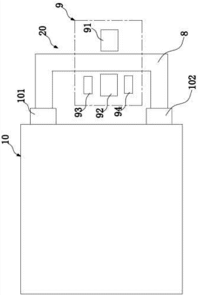
[0060] The automatic transfer and loading and unloading device 20 for high temperature forming molds of the present invention will be described below with reference to the accompanying drawings. figure 1 As shown, it includes a forming mold conveying mechanism 8 and a discharging and loading station 9.
[0061] The forming mold conveying mechanism 8 is respectively matched with the feeding end 101 and the discharging end 102 of the processing equipment, and is used to transfer the forming mold with a temperature of not less than 100°C from the discharging end 101 of the processing equipment to the unloading and feeding Station 9 and from the unloading and loading station 9 to the feeding end 102 of the processing equipment; the forming mold conveying mechanism 8 can be various known conveying structures, such as a belt conveyor line or a six-axis mobile manipulator or having The linear guide rail and other structures of the forming mold placement structure are not limited here.
[0062] The unloading and loading station 9 is set at a position between the feeding end 101 and the discharging end 102 of the processing equipment, and includes an upper mold moving device 91 and a piece taking and setting device 92. The upper mold moving device 91 is used to raise and lower the upper mold of the forming mold 4 to control the opening and closing of the forming mold; the upper mold moving device 91 can be of various known structures, such as a vacuum suction device arranged on a cylinder, which is arranged on a multi-axis The clamping jaws on the moving mechanism, etc., are not limited here; the piece taking and placing device 92 is used to take out the molded piece from the lower mold of the molding mold and place it in the finished product placement area 93 in the mold-opening state, and remove it from the processing The piece placement area 94 takes the pieces and places them on the lower mold. The piece taking and placing device 92 can be of various known structures, such as a vacuum suction structure set on a multi-axis moving structure or a multi-axis moving structure. The structure of the gripper is not limited here.
[0063] In addition, in order to avoid heat consumption after the forming mold is output by the processing equipment, the contact area between the forming mold conveying mechanism 8 and the upper mold moving device 91 and the forming mold 4 is made of thermal insulation material, and the forming mold conveying mechanism 8 , The unloading and loading station 9 is located in the thermal insulation environment (not shown in the figure).
[0064] The high-temperature forming mold automatic transfer and loading and unloading device 20 also includes various positioning sensors for determining the position where the forming mold moves and for the unloading and loading station to determine the location and placement of the molded part and the workpiece to be processed ( (Not shown in the figure), so as to ensure the reliability and accuracy of the position movement of each part.
[0065] The above-mentioned automatic transfer and loading and unloading devices for high-temperature forming molds can be used with various equipment that needs to heat the molds and output equipment to discharge and load materials and send them to the equipment for heat forming again, thereby realizing the automation of the entire processing process.
[0066] Further, the present invention discloses a high-efficiency 3D flat panel cover glass processing system, which is preferably used for processing 3D mobile phone cover glass, 3D tablet computer cover glass, liquid crystal display glass, etc., as attached figure 1 As shown, it includes the hot bending machine 10 and the aforementioned high-temperature forming mold automatic transfer and loading and unloading device 20, although the feeding end 101 and the output end 102 of the hot bending machine 10 shown in the figure are located on the same side of the hot bending machine, However, their specific arrangements can be set according to actual needs, and are not limited here.
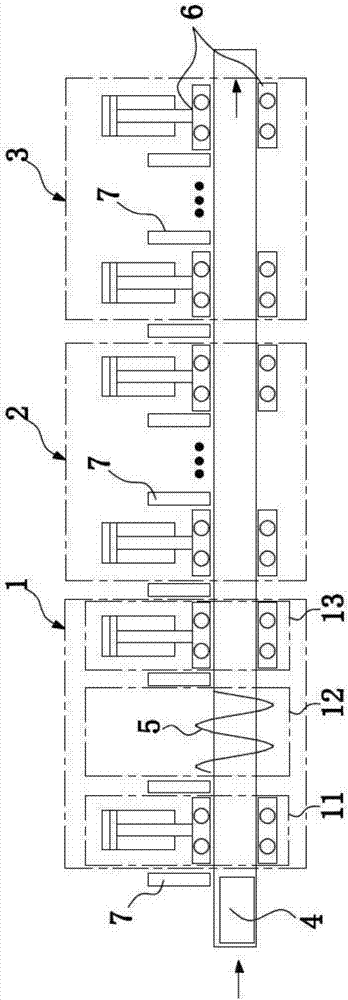
[0067] As attached figure 2 As shown, the hot bending machine 10 includes a preheating station 1, and the preheating station 1 includes at least a second preheating station 12 that uses electromagnetic induction heating equipment 5 for heating, and a gap set behind it. The resistance heating device 6 performs heating at the third preheating station 13.
[0068] Wherein, the electromagnetic induction heating device 5 includes at least a ring-shaped induction coil and a power supply device connected to the induction coil and providing alternating current for it. The induction coil can be connected to a lifting structure, so that it is preferably graphite When the material forming mold 4 is moved to the heating position, the induction coil is lowered to cover the forming mold 4 for heating. After the heating is completed, the induction coil rises to allow the forming mold 4 to move.
[0069] Of course, in other embodiments, the induction coil may also have a structure that extends a certain length and is fixed on the outer periphery of the forming mold conveying line. When the forming mold is moved into the hollow cavity, it is heated, and it is no longer heated when it is removed. There is no restriction on the specific layout of the induction coil.
[0070] In addition, the electromagnetic induction heating device 5 is preferably a high-frequency induction heating device, usually with a frequency above 10 kHz, which is a high frequency. In this solution, the induction frequency is preferably between 30 kHz and 80 kHz, so as to quickly generate a severe heat source to achieve rapid heating. The voltage of the electromagnetic induction heating device 5 is 380VAC, and the power of the power supply device can be adjusted according to actual process requirements. For example, when the mold needs to be raised by 300-400°C within 10s, the power can be selected as 20KW. Generally speaking: The shorter the time, the higher the temperature rise, and the greater the power required by the power supply device.
[0071] In addition, in another embodiment, a resistance heating device 6 can be added at the second preheating station 12 for heating according to actual needs, so that electromagnetic induction heating and resistance heating can be combined to further increase the heating rate.
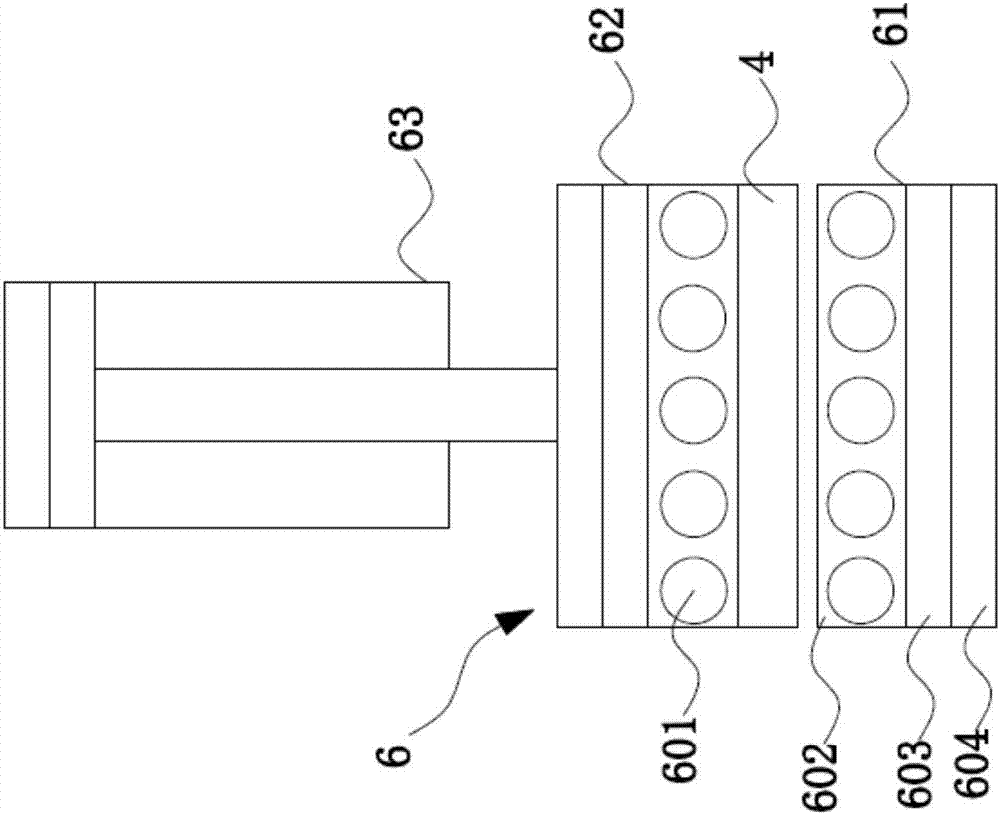
[0072] As attached image 3 As shown, the resistance heating device 6 includes a fixed position lower heating module 61 and a liftable upper heating module 62. Preferably, the lower heating module 61 is fixed below the carrier plate for carrying the forming mold 4. The heating module 62 and the lower heating module are arranged coaxially. Of course, the specific location, layout, and number of the lower heating module 61 and the upper heating module 62 can be adjusted according to actual needs, such as on both sides of the carrier plate. The lower heating module 61 is provided, or the upper heating module 62 is multiple and enclosed in a trough shape, etc., which is not limited here.
[0073] Furthermore, the lower heating module 61 and the upper heating module 62 both include a heating block 602 with a built-in resistance rod heating tube 601, and the side of the heating block 602 facing away from the forming mold 4 is provided with a heat insulation device 603, so The heat insulation device 603 is connected to the heat dissipating device 604, and the heat dissipating device 604 of the upper heating module 62 is connected to a driving device that drives the lifting device. Preferably, the driving device is an air cylinder. Of course, other feasible structures are also possible, which are not limited here.
[0074] The heat insulation device 603 is a stainless steel body or a super alloy body that is in line contact and/or multi-point contact with the heating block 602, for example, it is a ring structure, a tubular structure, or multiple independent and vertical support rods to the plane of the heating block The structure, etc., are not limited here, so that the contact area with the heating block 602 can be reduced, and the heat loss of the heating block 602 due to heat conduction can be reduced; the heat dissipation device 604 is mainly used to block the heat insulation device 603 and the driving device The heat conduction can prevent the position where the cylinder is connected to the upper heating module from being deformed due to excessive heating, which will increase the error during pressing. The heat sink 604 is a cooling device using coolant, preferably a water cooling device.
[0075] At the same time, the inventor discovered that if the electromagnetic induction heating device 5, that is, the second preheating station 12 is directly set at the feeding end of the hot bender, there will be a higher temperature at the feeding end during operation. It is not conducive to the operation of operators. Furthermore, due to the speed block of electromagnetic induction heating, the temperature change range is large. Therefore, the heating rate of the forming mold and the flat cover glass from the initial temperature to the target temperature in a short time is extremely high. It may exceed the heating rate range that the forming mold and the flat cover glass can withstand, causing adverse effects. Therefore, it is preferable that the front end of the second preheating station 12 is also provided with a first heating device 6 heated by the resistance heating device 6 described above. A preheating station 11, so the overall structure of the preheating station 1 is: the first preheating station 11 and the second preheating station 11 and the second preheating station are arranged in sequence from the feed end 101 to the rear and are heated by the resistance heating device 6 Position 12 and the third preheating station 13.
[0076] The entire preheating station 1 is usually set up with 3-5 gaps. The specific number of stations can be designed according to different process requirements. By increasing the number of preheating stations, it is beneficial to reduce the molding die in each station. The staying time, but it also increases the equipment manufacturing cost and the difficulty of control. The adjustment of the specific number of stations of the preheating station 1 is achieved by adjusting the number of substations of the third preheating station 13, preferably The number of sub-stations is 1-3, more preferably 2-3, and when the third preheating station is a plurality of sub-stations, and when the second preheating station 12 makes When the forming mold 4 is heated above the softening point temperature of the flat cover glass, the sub-stations of the third preheating station can also be gradually reduced, so that the temperature of the forming mold 4 is uniformly reduced to the softening point temperature.
[0077] When the hot bending machine 10 of the present invention is not used in conjunction with the high temperature forming mold automatic transfer and loading and unloading device 20, the temperature change curve at the preheating station is as attached Figure 4 As shown, the first preheating station 11 heats the forming mold and the flat cover glass in its heating area to a certain temperature at a relatively low heating rate, and there is still a certain gap between the temperature and the target temperature. The temperature at the inlet end is much lower, and when electromagnetic induction heating is performed at this time, the temperature change range is relatively reduced, and the heating rate is much lower under the condition that the heating time of a station remains unchanged.
[0078] Then through the second preheating station 12 at a higher heating rate, the forming mold is heated in a short time to not lower than the softening point temperature of the flat cover glass, as attached Figure 4 As shown, the forming mold is heated to above the softening point temperature of the flat cover glass, and the specific heating temperature is adjusted between 700-800°C according to the softening point of the flat cover glass and the graphite size.
[0079] Then the third preheating station 13 makes the temperature of the forming mold 4 slowly drop from the maximum temperature of the second preheating station 12 to the softening point temperature of the flat cover glass and then maintains it for a period of time, as attached image 3 As shown, of course, if the forming mold is only heated to the softening point temperature of the flat cover glass in the second preheating station 12, the forming mold is directly held on the flat cover glass at the third preheating station 13. Softening point temperature.
[0080] After electromagnetic induction heating, the temperature distribution of the forming mold is not uniform. The temperature in the area close to the electromagnetic coil is higher, and the temperature far away is relatively low, that is, there is a temperature difference between the edge temperature and the center temperature of the forming mold, so in the third preheating When station 13 adopts resistance heating equipment for subsequent heating, since the resistance heating equipment and the two axial surfaces of the molding die are more closely aligned, there is no deviation, so the upper and lower surfaces of the molding die can be heated as a whole, thereby making the molding The temperature distribution of the mold is evened, so that all parts of the flat cover glass are evenly heated to reach the softening point temperature, so as to prevent the flat cover glass from being easily crushed due to the partial failure of the softening point in the subsequent pressing process. Or excessive deformation of the flat cover glass due to local overheating occurs; and, during the heating process of the first preheating station 11, the second preheating station 12 and the third preheating station 13, the upper heating The module 62 does not apply pressure to the molding die 4.
[0081] After preheating, as attached figure 2 , Attached Figure 4 As shown, the forming mold 4 equipped with the flat cover glass will be pressed by the forming station 2 and cooled and shaped at the cooling station 3. The forming station 2 includes at least one single pressing station, preferably 3. Each pressing station is heated by the above-mentioned resistance heating device 6 and the flat cover glass is kept at the softening point temperature. While heating, the upper heating module 62 is applied to the upper part of the forming mold 4. The template exerts pressure to deform the flat cover glass.
[0082] The cooling station 3 maintains a gap with the molding station 2, which also includes at least one separate cooling station, preferably 3-4 with gaps, each cooling station also uses resistance heating equipment 6 for molding The cooling of the mold 4, and the temperature of the resistance heating device 6 of each cooling station is lower than the temperature of the forming mold 4, and the temperature of the resistance heating device 6 of the multiple cooling stations is decreasing; while cooling, each cooling station The upper heating module 62 also applies pressure to the flat cover glass.
[0083] In the whole process, as attached figure 2 As shown, in order to realize the movement of the forming mold 4 in each station and between the stations in each station in turn, the hot bending machine further includes a conveying device, and the conveying device may be in various known forms and Structure, in this solution, it is preferred that it at least includes the above-mentioned bearing plate that penetrates each station of the preheating station, the forming station and the cooling station, and each station is provided with a supporting plate for driving the forming mold A movable toggle mechanism, the toggle mechanism is located at the gap between adjacent stations, which includes a toggle lever 7, a cylinder (not shown in the figure) that drives the toggle lever 7 up and down, and a drive lever 7 in A translation mechanism composed of a motor and a lead screw (not shown in the figure) that moves between stations; when there is no need to push the forming mold, the cylinder is in a retracted state, and the shift lever 7 is in a retracted state; It is necessary to push the forming mold, the telescopic shaft of the cylinder extends, so that the shift rod moves down to the side position of the forming mold, and then the servo motor drives the lead screw to drive the shift rod to move in translation to realize the push of the mold .

PUM

no PUM

Description & Claims & Application Information

We can also present the details of the Description, Claims and Application information to help users get a comprehensive understanding of the technical details of the patent, such as background art, summary of invention, brief description of drawings, description of embodiments, and other original content. On the other hand, users can also determine the specific scope of protection of the technology through the list of claims; as well as understand the changes in the life cycle of the technology with the presentation of the patent timeline. Login to view more.

Similar technology patents

Foldable gliding frame and foldable scooter

Owner:苏州速蝶科技有限公司

High-precision fully-automatic cutting device and method thereof

Owner:昆山新井田智能设备有限公司

Wet garbage treatment device and wet garbage treatment method

Owner:环川环保设备(苏州)有限公司

Battery core stacking clamp

Owner:SUZHOU JEE INTELLIGENT EQUIP CO LTD

Classification and recommendation of technical efficacy words

  • Simple structure
  • exquisite design

Sharing system for air-conditioning coat

InactiveCN107440179ASimple structureeasy to wear
Owner:QINGDAO HAIER AIR CONDITIONER GENERAL CORP LTD

Feeding device of sorter of batteries plate

InactiveCN101357717ASimple structurecooperate well
Owner:NANJING NORMAL UNIVERSITY

Emergency parachuting device and method for multiple-rotor unmanned aerial vehicle

InactiveCN103895870Aavoid aircraft crashSimple structure
Owner:SOUTH CHINA AGRI UNIV +1

Intelligent luminous cup

InactiveCN103126456Aeasy to useexquisite design
Owner:TAIZHOU QIBANG IND DESIGN

Temperature difference energy driven ocean section movement system

InactiveCN105952691AIncrease the frequency of exerciseexquisite design
Owner:ZHEJIANG UNIV

Anti-theft label

InactiveCN101339686AImprove anti-theft functionexquisite design
Owner:ORLEN SENTINEL INDAL SHANGHAI
Why Eureka
Try Eureka