Method for calibration of parabolic catadioptric camera by employing ball image and common self-polar triangles

A triangular, catadioptric technique used in computer vision

Active Publication Date: 2018-04-06
YUNNAN UNIV
View PDF10 Cites 15 Cited by
  • Summary
  • Abstract
  • Description
  • Claims
  • Application Information

AI Technical Summary

Problems solved by technology

The document "Catadioptric camera calibration using geometric invariants", (Ying X., Hu Z., IEEE Transactions on Pattern Analysis and Machine Intelligence, 26(10): 1260-71, 2004) uses

Method used


Image

  • Method for calibration of parabolic catadioptric camera by employing ball image and common self-polar triangles
  • Method for calibration of parabolic catadioptric camera by employing ball image and common self-polar triangles
  • Method for calibration of parabolic catadioptric camera by employing ball image and common self-polar triangles

Examples


Embodiment

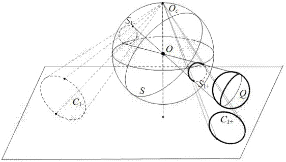
[0072] The invention proposes a method for linearly solving the internal parameters of a parabolic catadioptric camera by using a sphere in space as a calibration object. The experimental template structural schematic diagram that the present invention adopts is as figure 1 shown. The embodiment of the present invention will be described in more detail with an example below.

[0073] The experimental template used in the calibration of the parabolic catadioptric camera is a sphere in space, such as figure 1 As shown, the ball is Q. Utilize the method among the present invention to carry out calibration for the parabolic catadioptric camera that is used for experiment, concrete steps are as follows:

[0074] 1. Fitting mirror profile projection equation, spherical image equation

[0075] The image size used in the present invention is 1590×1296. Use a parabolic catadioptric camera to shoot three images of a ball in different positions in space, read in the images, use the ...


PUM


Abstract

The present invention relates to a method for calibration of a parabolic catadioptric camera by employing a ball image and common self-polar triangles. A ball in a space is employed as a calibration object to fit a mirror surface contour projection equation and a ball image equation under a parabolic catadioptric camera and calculate an antipodal ball image equation and an equation of an image ofa great circle having a center of a circle being coincided with a center of a circle of a unit virtual ball and being parallel with a projection small circle of the ball on a unit visual ball model, two common poles, corresponding to two common self-polar triangles formed by the ball image and the antipodal ball image, of the image of the great circle are connected with two common poles to solve avanishing line, a relation of the projection of the circle and the vanishing line is employed to solve the images of circular ring points, and three images are shot to obtain images of the three circular ring points, and the images of the circular ring points and the constraint of the internal parameter matrix of the camera are employed to complete calibration of the camera.

Description

technical field [0001] The invention belongs to the field of computer vision and relates to a method for solving internal parameters of a parabolic catadioptric camera by using a sphere in space and a common self-polar triangle. Background technique [0002] Computer vision is to simulate human vision by computer to identify, detect and track targets. The tasks of computer vision include acquiring, processing, analyzing and understanding digital images, applying image processing and analysis techniques, transforming three-dimensional information obtained from space into two-dimensional planes, and recovering three-dimensional spatial information by analyzing the information of two-dimensional plane images, It enables computers to recognize the three-dimensional world from two-dimensional images, and thus recognize and detect objects. [0003] With the development of computer vision technology, higher requirements are put forward for cameras. Traditional cameras are difficu...

Claims


Application Information

Patent Timeline
IPC IPC(8): G06T7/80
CPCG06T2207/20068G06T7/85
Inventor 赵越于晓娟余星华谢小光
Owner YUNNAN UNIV
Why Eureka
Try Eureka