Last stage safe flow monitoring and control system and method

A flow monitoring and control system technology, applied to steam engine devices, engine components, machines/engines, etc., can solve problems such as long-term and large-scale operation, and achieve the effect of simple structure

Pending Publication Date: 2018-04-13
THERMAL POWER TECH RES INST OF CHINA DATANG CORP SCI & TECH RES INST
View PDF0 Cites 5 Cited by
  • Summary
  • Abstract
  • Description
  • Claims
  • Application Information

AI Technical Summary

Problems solved by technology

In order to improve energy utilization efficiency and heating economy, realize energy saving, water saving and harmful gas emission reduction, the waste heat utilization of heating units has been developed rapidly in recent years, but limited by the water flow and return water parameters of the heating network, the current double back Compressed double-rotor technology, low-pressure cylinder optical shaft technology, and absorption heat pump technology can only recover the waste heat of one unit. How to minimize the waste heat of the steam turbine and improve the pow

Method used


Image

  • Last stage safe flow monitoring and control system and method

Examples


Example Embodiment

[0034] The specific embodiments of the present invention will be described in further detail below in conjunction with the drawings and embodiments. The following examples are used to illustrate the present invention, but not to limit the scope of the present invention.
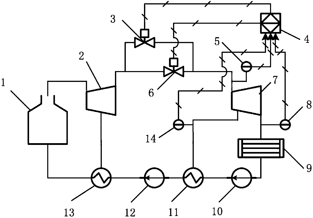
[0035] Participate figure 1 As shown, this embodiment provides a last-stage safe flow monitoring and control system for monitoring and controlling the minimum safe flow of the last stage of a steam turbine. The system includes a boiler 1, a steam turbine high-pressure cylinder 2, a steam turbine low-pressure cylinder 7, a condenser 9, Condensate pump 10, low pressure heater 11, feed water pump 12, high pressure heater 13, steam turbine low pressure cylinder intake regulating valve 6, controller 4, turbine low pressure cylinder inlet steam parameter measurement table 5, steam turbine low pressure cylinder extraction steam parameter measurement table 14 , Turbine low pressure cylinder exhaust steam pressure measu...


PUM


Abstract

The invention belongs to the technical field of steam turbines, and in particular relates to a system and method for monitoring and controlling the final safety flow rate of a steam turbine. Cylinder exhaust pressure value, and according to the pressure value, set the allowable low-pressure cylinder inlet steam parameter and/or low-pressure cylinder extraction parameter value range, and the actual value of the low-pressure cylinder inlet steam parameter and/or low-pressure cylinder extraction parameter The measured values ​​are compared, and when the actual measured value exceeds the allowable value range, the steam intake of the low-pressure cylinder of the steam turbine is adjusted so that the actual measured value is within the allowable value range. The invention effectively solves the problem of monitoring, adjusting and controlling the minimum safe flow rate of the final stage of a large steam turbine, can ensure the safe and economical operation of the unit, and the system has the characteristics of simple structure, safety and reliability.

Description

technical field [0001] The invention belongs to the technical field of steam turbines, in particular to a system and method for monitoring and controlling the safety flow of the final stage of a steam turbine. Background technique [0002] Steam turbine is the main driving equipment of large rotary equipment, especially generators, and it is widely used in modern industry, especially in the field of power generation. With the increase of unit capacity of power generation equipment, the length of the final stage blade of the steam turbine gradually increases, and the longer final stage blade will induce flutter under the small volume flow rate, and eventually lead to fatigue fracture of the blade, which seriously threatens the safe operation of large steam turbines. [0003] Usually steam turbine manufacturers stipulate a minimum safe volumetric flow rate during the design process of long blades, and take measures to ensure that the actual flow rate of the final stage of the ...

Claims


Application Information

Patent Timeline
IPC IPC(8): F01K7/04F01K7/02F01K7/38F01K7/40F01D17/00
CPCF01D17/00F01K7/02F01K7/04F01K7/345F01K7/38F01K7/40Y02P90/02
Inventor 万逵芳刘岩张振华崔彦亭邓爱祥赵文波宋寅胥佳瑞周雅君吴韬
Owner THERMAL POWER TECH RES INST OF CHINA DATANG CORP SCI & TECH RES INST
Why Eureka
Try Eureka