Radial efficient powder selecting machine and design method of powder selecting machine

A design method and technology of a powder separator, which are applied in chemical instruments and methods, solid separation, and separation of solids from solids by airflow, which can solve the problem of increasing airflow resistance, increasing powder separation resistance loss, and increasing system power consumption. and other problems, to achieve the effect of high powder selection efficiency, low resistance, and wide gradation of finished particles.

Pending Publication Date: 2018-04-17
TIANJIN CEMENT IND DESIGN & RES INST
View PDF5 Cites 9 Cited by
  • Summary
  • Abstract
  • Description
  • Claims
  • Application Information

AI Technical Summary

Problems solved by technology

[0007] According to industrial production practice and theoretical analysis, the principle of the three-force balance powder separator mainly has the following deficiencies: 1) In the working state, the moving blade 1 follows the rotation of the rotor 2, driving the airflow passing through the gap between the moving blades to rotate, and under the action of centrifugal force, the moving blade 1 is located on the moving blade. The airflow in the gap between the blades will generate centrifugal dynamic pressure, which will increase the flow resistance of the subsequent airflow, that is, increase the resistance loss of powder selection; 2) Particle drag force F d There is no obvious relationship with the speed of the powder separator (in theory, strictly speaking, it decreases with the increase of the speed of the powder separator), and the centrifugal force F c It is directly proportional to the square of the speed of the powder classifier, so the efficiency of powder selection decreases with the increase of the speed of the powder classifier, especially when sorting high-fineness finished products such as cement, this phenomenon is more obvious, thereby reducing the grinding speed. efficiency and increase system power consumption

Method used


Image

  • Radial efficient powder selecting machine and design method of powder selecting machine
  • Radial efficient powder selecting machine and design method of powder selecting machine
  • Radial efficient powder selecting machine and design method of powder selecting machine

Examples


Embodiment 1

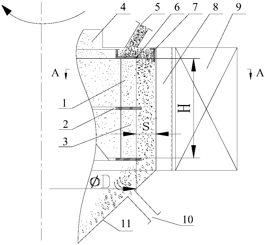
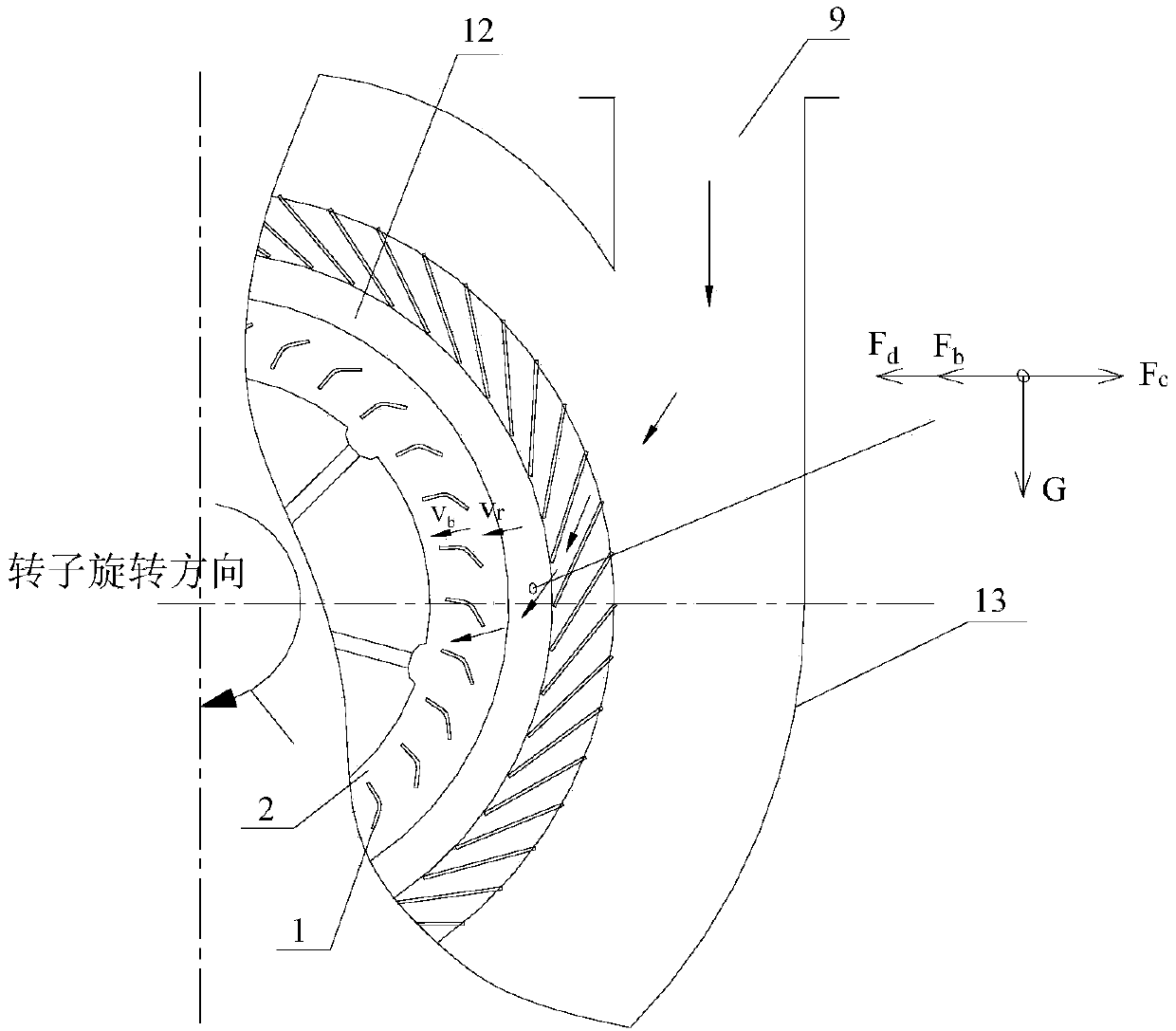
[0056] Example 1, see figure 1 and figure 2 , a centripetal high-efficiency powder separator, comprising a powder separator housing 13, a finished product outlet 4 arranged on the upper part of the powder separator; an air inlet connected to the powder separator casing and a feeding port 5 arranged on the upper part; corresponding to feeding There is a material spreading plate 6 in the shell of the powder separator at the position of the material opening, and a material buffer plate 7 is provided at the corresponding position of the material spreading plate. The coarse powder collecting cone 11 located at the lower end of the powder separator shell is provided with three times Air inlet 10; the powder separator rotor 2 installed in the powder separator housing is provided with the upper and lower moving blades of the powder separator rotor. The blades are named as two-stage moving blades 3, and stationary blades are installed on the powder separator housing corresponding to...

Embodiment 2

[0107] Example 2, see Figure 8 and Figure 9 , a centripetal high-efficiency powder separator, including a powder separator shell 13, a finished product outlet 4 arranged on the upper part of the powder separator; connecting the air inlet 9 and the feeding port 5 of the powder separator shell, this model belongs to The air inlet and the feeding port of the prior art are the same; the feeding port is on the side of the powder separator shell; the coarse powder collecting cone located at the lower end of the powder separator shell is provided with a tertiary air blower on the coarse powder collecting cone. Entrance 10; the powder separator rotor 2 installed in the powder separator housing, the upper and lower moving blades of the powder separator rotor are set, and the upper moving blade is named as a section of moving blade 1 for convenience of explanation, and the lower moving blade Named as the second-stage moving blade 3, the powder separator shell is equipped with a stati...

Embodiment 3

[0108] Example 3, see Figure 10 and Figure 11 , a centripetal high-efficiency powder separator, including a powder separator shell 13, a finished product outlet 4 arranged on the upper part of the powder separator; connecting the air inlet 9 and the feeding port 5 of the powder separator shell, this model belongs to The air inlet and the feeding port of the prior art are the same; the feeding port is at the lower end of the powder separator shell; the coarse powder collecting cone located at the lower end of the powder separator shell; The powder separator rotor 2 in the machine housing is provided with the upper and lower movable blades of the powder separator rotor. For the convenience of explanation, the upper movable blade is named as the first-stage movable blade 1, and the lower movable blade is named as the second-stage movable blade 3 , corresponding to the position of the moving blade, a static blade is installed on the shell of the powder selector; the moving blad...


PUM


Abstract

The invention relates to a radial efficient powder selecting machine. The radial efficient powder selecting machine comprises a powder selecting machine shell, a finished product outlet formed in theupper part of the powder selecting machine, an intake port and a feed port connected to the powder selecting machine shell, a thick powder collecting cone positioned at the lower end of the powder selecting machine shell, a powder selecting machine rotor mounted in the powder selecting machine shell, movable blades arranged above and below the powder selecting machine rotor, and static blades mounted on the powder selecting machine shell and opposite to the movable blades; the movable blades comprise outer wind fin sections and inner wind fin sections; and the outer wind fin sections and the inner wind fin sections are in arc transition. The invention further provides the radial efficient powder selecting machine and a design method of the powder selecting machine. The technical effects ofthe radial powder selecting machine synthesize CFD theoretical analysis, laboratory tests and industrial application production data, and mainly embody on such aspects as low resistance, high powderselecting efficiency and high selecting clearness.

Description

technical field [0001] The invention belongs to the technical field of grinding, and in particular relates to a centripetal high-efficiency powder separator and a design method of the powder separator. Background technique [0002] The powder separator technology has developed with the application of the circular flow ball mill system, and has experienced centrifugal powder separator (first generation), cyclone powder separator (second generation), high-efficiency cage powder separator (third generation) development process. The high-efficiency cage-type powder separator was first invented by Japan's Onoda Company in 1979, and then it was widely used in the grinding system of various materials and products of various fineness in the ball mill and vertical mill system. In 1987, the China National Building Materials Bureau organized the introduction of this item. technology. Over the past 30 years since the cage-type powder separator came out, its structure has undergone man...

Claims


Application Information

Patent Timeline
Patent Type & Authority Applications(China)
IPC IPC(8): B07B7/083
CPCB07B7/083
Inventor 豆海建王维莉王文荟杜鑫贺孝一张明飞秦中华
Owner TIANJIN CEMENT IND DESIGN & RES INST
Why Eureka
Try Eureka