Motor vehicle internal combustion engine speed-sensitive linear automatic supercharging air supply device

An air supply device and internal combustion engine technology, applied in the direction of machines/engines, fuel air intake, combustion air/combustion-air treatment, etc., can solve the problem of small diameter, increased vehicle cost and maintenance costs, and unsmooth air supply, etc. question

Active Publication Date: 2018-04-17
HONGHE COLLEGE
View PDF8 Cites 0 Cited by
  • Summary
  • Abstract
  • Description
  • Claims
  • Application Information

AI Technical Summary

Problems solved by technology

The mechanical supercharging method not only consumes a lot of fuel, but also increases the cost of the motor vehicle and the maintenance cost; the cost of the motor vehicle increased by adding a gas exhaust turbocharger is about 10,000 yuan, and it also increases the subsequent maintenance cost
Since the entire air supply channel of the turbocharger, together with the cooling system, has a total path of two or three meters, the diameter is thin, and the path is not smooth and smooth, so the entire air supply is not smooth before the supercharging intervenes.
Insufficient air supply and suboptimal efficiency of internal combustion engines

Method used


Image

  • Motor vehicle internal combustion engine speed-sensitive linear automatic supercharging air supply device
  • Motor vehicle internal combustion engine speed-sensitive linear automatic supercharging air supply device
  • Motor vehicle internal combustion engine speed-sensitive linear automatic supercharging air supply device

Examples


Embodiment Construction

[0041] The implementation process and beneficial technical effects of the present invention will be further described below in conjunction with the accompanying drawings, but the protection scope of the present invention is not limited by these examples.

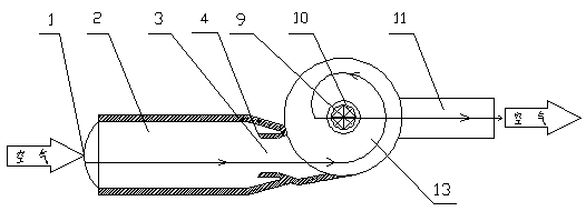
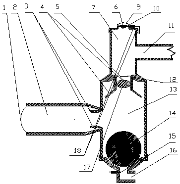
[0042] Take the speed-dependent linear self-increasing air supply device of a motor vehicle internal combustion engine with compound pressurization chamber as an example. Such as Figure 1-5As shown, the booster chamber 13 is a cylinder made of metal material or plastic, and the air inlet 2 is a tube of the same material with a slightly thinner diameter, which is connected to the booster chamber in a tangential direction so that the air enters in a spiral manner. rise. The bottom of the pressurization chamber is spherical and has a sewage outlet 16 in the center to facilitate the discharge of water droplets, dust particles and other dirt agglomerated in the pressurization chamber. A rubber cortex hollow plugging ball 14 is...


PUM


Abstract

The invention provides a motor vehicle internal combustion engine speed-sensitive linear automatic supercharging air supply device. The air supply device is provided with a supercharging chamber communicating with an air inlet pipe of an internal combustion engine. An air inlet of the supercharging chamber faces against the wind generated by a motor vehicle during advancing, and the air pressure in the supercharging chamber and the air supply amount of the internal combustion engine are automatically increased and reduced along with change of the vehicle speed. The supercharging chamber can beof a combined structure, or an eggshell type structure, a whistle type structure, or a horn type structure or a straight pipe type structure. The combined supercharging chamber is composed of a supercharging chamber body and an auxiliary supercharging chamber body on the upper portion. A valve grid is arranged between the supercharging chamber body and the auxiliary supercharging chamber body. Anair pressure valve is arranged on the valve grid and is limited between guide rods to float up and down. The upper end of the auxiliary supercharging chamber body is provided with an auxiliary air inlet used for being sealed when the air pressure valve floats up. An internal combustion engine air inlet pipe communicates with the auxiliary supercharging chamber body. A pipe serves as the air inletand goes into the supercharging chamber body in the tangential direction. Air is fed into the internal combustion engine through the wind pressure generated by the motor vehicle during running to increase the air supply amount and promote sufficient burning of fuel oil. The power of the internal combustion engine is increased. Oil consumption is reduced. Carbon deposit of the internal combustionengine is reduced. The purchase cost and the maintenance cost of the motor vehicle are reduced.

Description

technical field [0001] The invention belongs to a fuel-saving and efficiency-enhancing device, in particular to a speed-dependent linear self-supercharging air supply device for a motor vehicle internal combustion engine. Background technique [0002] If the air intake of the motor vehicle internal combustion engine is sufficient, the fuel combustion is sufficient. As the speed of motor vehicles increases, the power of the internal combustion engine is required to increase accordingly. The speed of the internal combustion engine increases the intake air volume or the oil supply volume needs to be increased accordingly. The naturally aspirated internal combustion engine relies on the speed to increase to generate a higher negative pressure to inhale and supply oxygen. The longer the intake passage, the higher the speed, the higher the negative pressure, and the greater the resistance when the air flows through the air passage, resulting in a lag in air supply instead of a l...

Claims


Application Information

Patent Timeline
Patent Type & Authority Applications(China)
IPC IPC(8): F02M35/10
CPCF02M35/10262
Inventor 张国伟冯绍平陈显兰金艳
Owner HONGHE COLLEGE
Why Eureka
Try Eureka