Thermoacoustic vibration suppression device for liquid helium container based on variable volume damping gas storage

A technology of thermoacoustic oscillation and suppression device, applied in pressure vessels, container filling methods, container discharge methods, etc., can solve the problems of increased evaporation loss of liquid helium, pressure and temperature fluctuations, and weakened thermoacoustic oscillation suppression effect, etc. Achieve the effect of good high pressure resistance, thermoacoustic oscillation suppression, and the best suppression effect

Active Publication Date: 2019-07-30
SHANGHAI JIAO TONG UNIV +1
View PDF11 Cites 0 Cited by
  • Summary
  • Abstract
  • Description
  • Claims
  • Application Information

AI Technical Summary

Problems solved by technology

[0005] (1) It causes fluctuations in the pressure and temperature in the container, and the excessive pressure amplitude may even endanger the structural stability of the container;
[0006] (2) The heat leakage of the liquid helium container increases sharply. For open containers, the evaporation loss of liquid helium will increase significantly; for closed containers, the pressure rise rate will be much higher than the design value. If the pressure is not effectively controlled, once Exceeding the pressure limit of the container will cause explosion and other safety accidents;
[0007] (3) The pressure and temperature fluctuations in the container will bring errors to the data measurement in the experimental liquid helium container, resulting in the inability to accurately monitor the internal state of the container
[0009] After searching the prior art, it was found that the Chinese patent "multi-resonant tube thermoacoustic engine" with the publication number CN101054960 and the Chinese patent "thermoacoustic drive unit, thermoacoustic engine and thermoacoustic heat pump system" with the publication number CN106762495 disclose the following A thermoacoustic engine for the purpose of generating and stimulating thermoacoustic oscillations converts thermal energy into mechanical energy, but the purposes of the two inventions are just opposite to the present invention and cannot be directly used
The Chinese patent "Combustor for Gas Turbine and Method for Reducing Thermoacoustic Oscillation in Gas Turbine" with authorized notification number CN105393057 proposes to reduce the occurrence of thermoacoustic oscillation in the combustor by adjusting the residence time curve of the fuel flow, But this method cannot be applied in the semi-closed tube of the liquid helium container without flow
The Chinese patent "An Acoustic Flame Tube with Damping Thermoacoustic Oscillation" with the publication number CN104676649 proposed a scheme of using a resonator to suppress the thermoacoustic oscillation in the combustion chamber, but the resonator in this scheme is not adjustable, so it can only be used for a specific The high-temperature thermoacoustic oscillation near the frequency plays an inhibitory role. When the operating conditions of the burner change, causing the thermoacoustic oscillation frequency to deviate from the natural frequency of the resonator, the thermoacoustic oscillation inhibition effect of this scheme will inevitably weaken or even fail.
The Chinese patent "Method and Device for Damping Thermoacoustic Oscillation Especially in Gas Turbine" with the authorized announcement number CN101263343 proposes to install a resonator on the brake of the combustion chamber and connect the resonator and the combustion chamber through two pipelines However, this method may lead to the formation of gas circulation between the combustion chamber and the resonator, resulting in a large amount of heat leakage, which is extremely unfavorable for liquid helium containers that require extremely high thermal insulation performance
In addition, the above-mentioned invention patents related to the suppression of thermoacoustic oscillations are all proposed for the high-temperature combustion process in the burner. Due to the huge difference between the burner structure, working temperature, working pressure, operating environment and thermal insulation performance requirements, and the liquid helium container, Therefore, the above schemes are not suitable for liquid helium containers

Method used


Image

  • Thermoacoustic vibration suppression device for liquid helium container based on variable volume damping gas storage
  • Thermoacoustic vibration suppression device for liquid helium container based on variable volume damping gas storage
  • Thermoacoustic vibration suppression device for liquid helium container based on variable volume damping gas storage

Examples


Embodiment Construction

[0026] Below in conjunction with embodiment and accompanying drawing, the present invention is described in detail, and present embodiment is carried out under the premise of technical solution of the present invention, has provided detailed implementation mode and specific operation process, but protection scope of the present invention is not limited to the following the described embodiment.

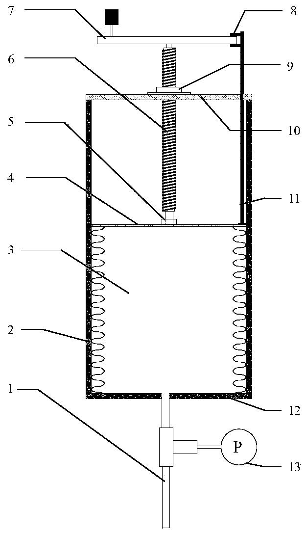
[0027] Such as figure 1 as shown, figure 1 It is a structural schematic diagram of Embodiment 1 of a thermoacoustic oscillation suppression device for a liquid helium container based on a variable volume damping gas storage of the present invention. As can be seen from the figure, the present invention is based on a variable volume damping gas storage device for liquid helium container thermoacoustic oscillation suppression, including a capillary 1, a gas storage sleeve 2, a damping gas storage 3, a moving plate 4, a screw fixed bearing 5, and a ball screw 6. Nut pair 9, lead screw ...


PUM


Abstract

The invention discloses a thermoacoustic oscillation suppression device based on a variable-volume damping gas storage for a liquid helium container. The thermoacoustic oscillation suppression devicecomprises a capillary tube, a gas storage sleeve, the damping gas storage, a moving plate, a screw rod fixing bearing, a ball screw, a nut pair, a screw nut fixing plate, a scaleplate, a gas storage fixing plate and a pressure sensor, wherein a corrugated pipe is adopted for the damping gas storage, so that the gas storage has the characteristics of being resistant to high pressure and high in sealing performance, and change for the volume of the damping gas storage can also be realized by virtue of the axial scalability of the corrugated pipe. Manual or automatic adjustment can be carried outon the volume of the gas storage according to the different use working conditions of the liquid helium container, so that the optimal suppression effect of the device for the thermoacoustic oscillation of the liquid helium container is guaranteed.

Description

technical field [0001] The invention relates to a liquid helium storage container, in particular to a thermoacoustic oscillation suppression device for a liquid helium container based on a variable volume damping gas store. [0002] technical background [0003] Due to the existence of necessary functions such as filling and exhausting of liquid helium storage containers or experimental containers, there must be pipelines connecting the room temperature environment and the cryogenic chamber. These pipelines are often equipped with a stop valve for on-off operation at the room temperature end, and are closed most of the time; the low temperature end is inserted into the inner tank of the liquid helium container and is in an open state. This kind of closed end is located in the room temperature environment, and the open end is in the semi-closed tube in the low temperature environment. Helium is very easy to spontaneously generate pressure oscillations, also known as thermoacou...

Claims


Application Information

Patent Timeline
Patent Type & Authority Patents(China)
IPC IPC(8): F17C1/00F17C13/00
CPCF17C1/00F17C13/00F17C2221/017F17C2223/013
Inventor 蒋文兵黄永华王如竹耑锐程光平张亮蒋赞
Owner SHANGHAI JIAO TONG UNIV
Why Eureka
Try Eureka