Infinite-endurance air power system and engine system thereof

An aviation aerodynamic and air compressor technology, which is applied to machines/engines, pressure vessels, mechanical equipment, etc., and can solve the problems of weak driving force and inability to achieve infinite battery life.

Pending Publication Date: 2018-04-20
曲阜市海华高科技有限公司
View PDF5 Cites 1 Cited by
  • Summary
  • Abstract
  • Description
  • Claims
  • Application Information

AI Technical Summary

Problems solved by technology

[0004] As the main driving mechanism of aerodynamics, existing aerodynamic equipment includes blade-type driving mechanisms, piston-type driving mechanisms, screw-type driving mechanisms, and fan-type driving mechanisms. The driving force of the aerodynamic vehicles using the above-mentioned driving mechanisms is quite weak , so only miniature scooters can be produced, and the displacement can only reach several hundred kilometers after being inflated for 4 hours, and it cannot achieve unlimited battery life.

Method used


Image

  • Infinite-endurance air power system and engine system thereof
  • Infinite-endurance air power system and engine system thereof
  • Infinite-endurance air power system and engine system thereof

Examples


Embodiment 1

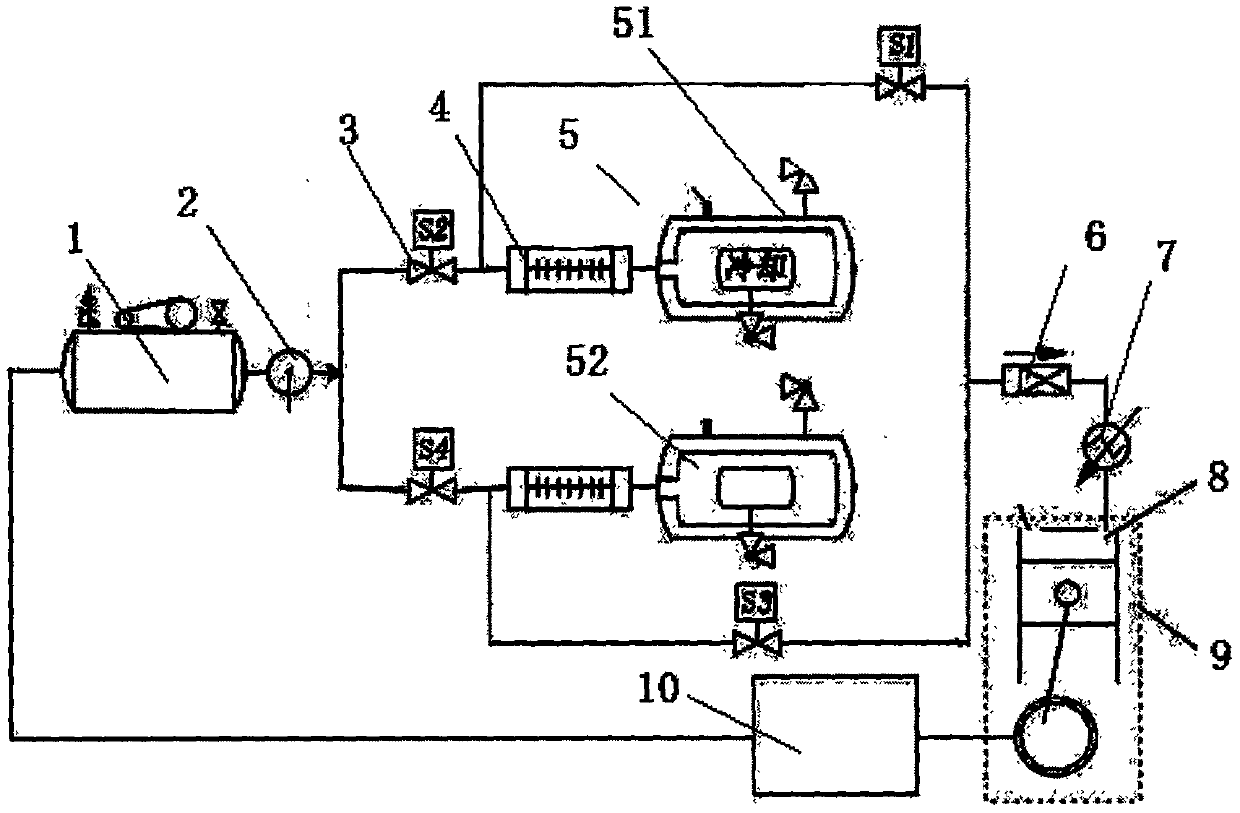
[0031] A kind of infinite cruising aerodynamic system of the present invention, see figure 1 As shown, it includes a miniature air compressor 1 and a plurality of air storage tanks 5, and the present embodiment is 2 air storage tanks 5, which are connected with the air compressor 1 through the air intake pipeline assembly, and through the electromagnetic valve on the air intake pipeline, Two air storage tanks 5 are controlled to inflate alternately, the air storage tanks 5 are connected to the air outlet pipeline assembly, and the two air storage tanks are controlled to supply air alternately through the electromagnetic valve on the air outlet pipeline.

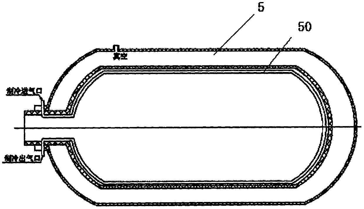
[0032] As preferably, a refrigeration heat exchange device 50 is provided on the inner wall of the air storage tank 5, which reduces the temperature of the inner tank, increases the accumulation of air molecules per unit volume, and improves the gas storage capacity of the air; further, in the intake air A heat exchanger 4 is...

Embodiment 2

[0041] see Figure 4 As shown, the piston used in the air compressor includes a piston body 13 and a piston ring. The piston body is composed of a piston head 16, a piston skirt 11 and a piston pin hole 12. The piston head 16 is provided with an upper gas ring groove 18 and a lower ring groove. The gas ring groove 19, the piston ring includes an upper piston ring and a lower piston ring, the piston skirt 11 is covered with a wear-resistant self-lubricating sheet 14, and the upper end surface of the upper gas ring groove 18 is provided with a ring around the upper gas ring groove 18. Planar air holes 17 are arranged, and the inner wall of the lower gas ring groove 19 is provided with vertical air holes 15 around the inner wall.

Embodiment 3

[0043] The present invention also provides an infinite-endurance aerodynamic engine system, including the above-mentioned infinite-endurance aerodynamic system providing aerodynamic force, air entering the aerodynamic engine, and the engine providing power for the transmission system 10 for the air compressor 1 to generate motion.


PUM


Abstract

The invention discloses an infinite-endurance air power system. The infinite-endurance air power system comprises a micro-type air compressor and two air storage tanks; each air storage tank is connected with the air compressor through an air intake pipeline assembly; the two air storage tanks are controlled to be charged with air alternately by virtue of electromagnetic valves on air intake pipelines; each air storage tank is connected with a corresponding air outlet pipeline assembly; and the two air storage tanks are controlled to supply air alternately by virtue of electromagnetic valves on air discharging pipelines. The invention aims to provide an air power system capable of infinitely providing air power; and meanwhile the invention also provides an air power engine system based onthe air power system, and the air power engine system can realize an infinite endurance function.

Description

technical field [0001] The invention relates to the technical field of new energy power, in particular to an aerodynamic system with unlimited endurance and an engine system using the above-mentioned power system. Background technique [0002] Aerodynamics uses a pneumatic engine to convert the pressure energy of high-pressure gas into mechanical energy to drive the displacement of related mechanical equipment. This displacement can be linear motion, circular motion, or curved motion. Compared with traditional internal combustion engines, aerodynamic engines no longer need to go through the high-temperature, high-pressure gas combustion process in the cylinder, but only need to do work through gas expansion to achieve the purpose of power output. [0003] The advantages of aerodynamically driven mechanical equipment are similar to those of solar vehicles, which can achieve an absolute "zero emission" state and eliminate environmental pollution; at the same time, its operatin...

Claims


Application Information

Patent Timeline
Patent Type & Authority Applications(China)
IPC IPC(8): F04B41/02F01B23/02F01B29/10F17C1/12F17C1/16
CPCF01B23/02F01B29/10F04B41/02F17C1/005F17C1/12F17C1/16
Inventor 韦静韦福旺
Owner 曲阜市海华高科技有限公司
Why Eureka
Try Eureka