
Sensing optical fiber and optical fiber sensing device

A technology for sensing optical fibers and optical fibers, which is applied to cladding optical fibers, measuring devices, optical waveguides, etc., can solve problems such as result errors, increased loss of sensing optical fiber interfaces, and increased workload, so as to reduce workload and avoid Increased interface loss and improved accuracy

Inactive Publication Date: 2018-04-20
BEIJING UNIV OF TECH
View PDF4 Cites 13 Cited by
  • Summary
  • Abstract
  • Description
  • Claims
  • Application Information

AI Technical Summary

Problems solved by technology

Since the sensing fiber needs to be reconnected every time a substance to be measured is detected, multiple times of fusion splicing and cutting of the sensing fiber will be performed when detecting a variety of substances to be measured, which will lead to Increased workload
At the same time, in the process of multiple fusion splicing and cutting of the sensing fiber, the loss of the sensing fiber interface will increase, resulting in errors in the detection results

Method used


Image

  • Sensing optical fiber and optical fiber sensing device
  • Sensing optical fiber and optical fiber sensing device
  • Sensing optical fiber and optical fiber sensing device

Examples


Embodiment Construction

[0024] The specific implementation manners of the present invention will be further described in detail below in conjunction with the accompanying drawings and embodiments. The following examples are used to illustrate the present invention, but are not intended to limit the scope of the present invention.

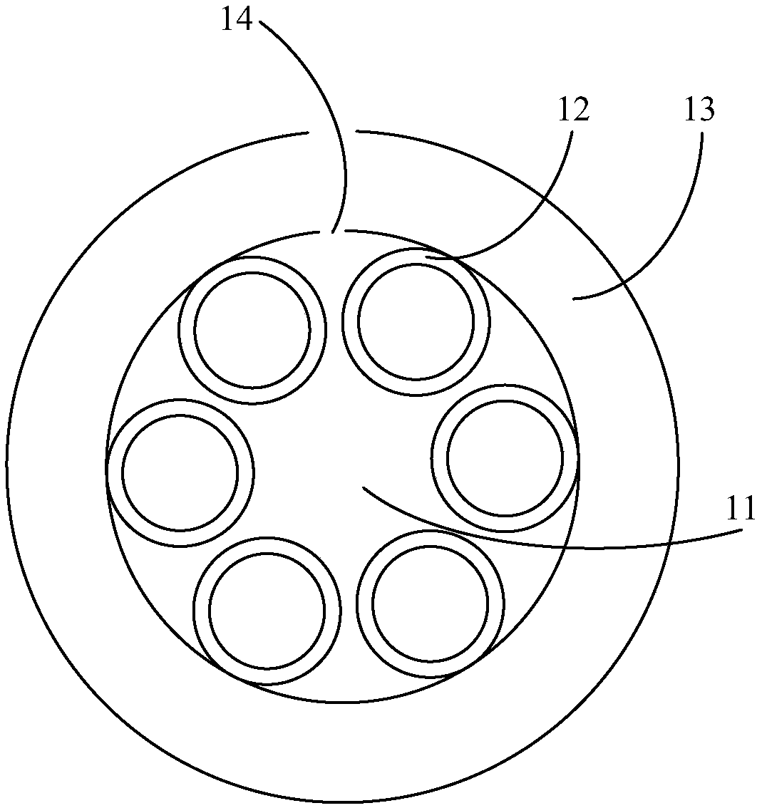
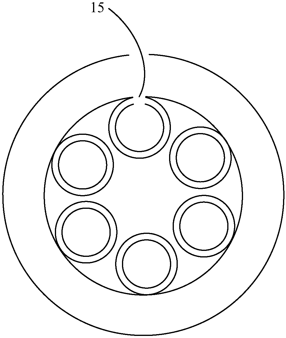
[0025] An embodiment of the present invention provides a sensing optical fiber, the sensing optical fiber is a hollow core antiresonant optical fiber; The core area surrounded by the area; the hollow tube is sleeved on the outside of the cladding area; the refractive index of the core area is lower than the refractive index of the cladding area; for the side of the hollow tube A plurality of preselected position groups, each preselected position group is provided with a through hole, and all preselected positions in each preselected position group are arranged along the central axis direction of the sensing fiber.

[0026] Specifically, the cladding region in the hollow-c...


PUM


Abstract

The invention provides a sensing optical fiber, and the optical fiber is a hollow anti-resonance optical fiber. The hollow anti-resonance optical fiber comprises a cladding region formed by a miniature capillary tube, a hollow tube, and a fiber core region which is surrounded by the cladding region. The hollow tube is disposed at an outer side of the cladding region in a cup joint manner. The refractive index of the fiber core region is lower than the refractive index of the cladding region. Each pre-selection position in each group of pre-selection positions on the side surface of the hollowtube is provided with a through hole, and all pre-selection positions in each group are arranged in the direction of the central axis of the sensing optical fiber. During the detection of various types of to-be-detected substances, the optical fiber can reduce the number of fusing and cutting times of the sensing optical fiber, reduces the workload of detection, and improves the accuracy of a detection result.

Description

technical field [0001] The invention relates to the technical field of optics and laser optoelectronics, more specifically, to a sensing optical fiber and an optical fiber sensing device. Background technique [0002] At present, with the development and progress of science and technology, optical fiber sensing technology has been widely used. Physical quantities such as temperature, pressure, flow, displacement, vibration, rotation, bending, liquid level, speed, acceleration, sound field, current, voltage, magnetic field and radiation are all sensed with different performances through optical fibers. [0003] Optical fiber sensing technology includes two functions of sensing and transmitting the substance to be measured. Sensing means that the external signal changes the physical characteristic parameters of the light wave transmitted in the optical fiber according to its changing law, such as intensity (power), wavelength, frequency, phase and polarization state, etc., an...

Claims


Application Information

Patent Timeline
Patent Type & Authority Applications(China)
IPC IPC(8): G01J3/12G01D5/26G02B6/02
CPCG01J3/12G01D5/268G02B6/02304
Inventor 王璞蒋东亮汪滢莹高寿飞
Owner BEIJING UNIV OF TECH
Learn More