Double-cylinder type sludge pump with discharging seal switching apparatus

A switching device and double-cylinder technology, which is applied to components of pumping devices for elastic fluids, multi-cylinder pumps, variable capacity pump components, etc. Shock, vibration, noise, complex shape of castings in the discharge chamber, etc., to achieve the effect of saving unit energy consumption, small reversing vibration impact, simple and reliable structure

Pending Publication Date: 2018-04-24
长沙紫宸科技开发有限公司
View PDF9 Cites 4 Cited by
  • Summary
  • Abstract
  • Description
  • Claims
  • Application Information

AI Technical Summary

Problems solved by technology

The S-tube switching structure device is adopted, the concrete and / or mud fluid pre-installed with the filler is sucked into the conveying cylinder by vacuum, the S-tube is swung, and the full-material conveying cylinder is connected with the conveying pipe, and the concrete and / or mud fluid is pressed in under the push of the piston In the conveying pipe, the fluid is conveyed; the hydraulic shock and vibration noise of the S pipe are very loud during the swing process, and the conveying pipe and the conveying cylinder cannot be arranged in a straight line due to structural reasons, and the fluid resistance of the plunger structure such as sludge is large. High energy consumption; structural wear caused by frequent switching of S tubes greatly reduces the reliability of the equipment
The lifting valve switching structure device is adopted. The feeding and discharging of the conveying cylinder are respectively controlled by two independent hydraulic cylinders pushing the cone valve. In the discharging structure of the lifting valve, the coaxial conveying of the conveying cylinder and the conveying pipe cannot be realized, and the flow resistance For large, non-Newtonian fluids, especially for fluids with a plunger structure such as sludge, the resistance of a bend is equivalent to the resistance of a pipeline with the same diameter of 10m; The shape is relatively complicated

Method used


Image

  • Double-cylinder type sludge pump with discharging seal switching apparatus
  • Double-cylinder type sludge pump with discharging seal switching apparatus
  • Double-cylinder type sludge pump with discharging seal switching apparatus

Examples


Embodiment Construction

[0022] The present invention will be further described in detail below in conjunction with the accompanying drawings and specific embodiments.

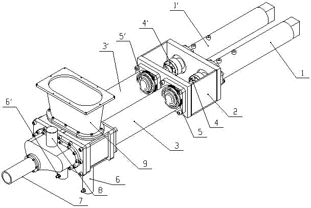
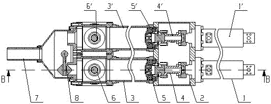
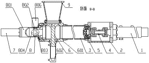
[0023] refer to figure 1 , figure 2 , this embodiment includes left main drive cylinder 1, right main drive cylinder 1', water tank 2, left conveying cylinder 3, right conveying cylinder 3', left connecting rod 4, right connecting rod 4', left concrete piston 5, right concrete Piston 5', left feeding device 6, right feeding device 6', conveying pipe 7, discharge seal switching device 8 and pre-installed filler 9; left main drive cylinder 1 is connected with left conveying cylinder 3 through water tank 2, left The piston rod of the main driving cylinder 1 is connected with the left concrete piston 5 through the left connecting rod 4, and the left concrete piston 5 and the left connecting rod 4 reciprocate in the left conveying cylinder 3 under the action of the left main driving cylinder 1; the right main driving cylinder 1' is conn...


PUM


Abstract

A double-cylinder type sludge pump with a discharging seal switching apparatus comprises a left main driving cylinder. The left main driving cylinder is connected with a left conveying cylinder via awater tank. A piston rod of the left main driving cylinder is connected with a left concrete piston via a left connecting rod. The left concrete piston and the left connecting rod perform reciprocating motion in the left conveying cylinder under the effect of the left main driving cylinder. A right main driving cylinder is connected with a right conveying cylinder via the water tank. A piston rodof the right main driving cylinder is connected with a right concrete piston via a right connecting rod. The right concrete piston and the right connecting rod perform reciprocating motion in the right conveying cylinder under the effect of the right main driving cylinder. A conveyer pipe is connected with the discharging seal switching apparatus. The discharging seal switching apparatus is connected with a left feeding device and a right feeding device. The left feeding device and the right feeding device are connected with a pre-filler. Exit resistance of a pumping system can be reduced, self-abrasion of the equipment during a pumping process can be reduced, equipment cost can be reduced, reliability of the equipment can be improved, and service lifetime of the equipment can be prolonged.

Description

technical field [0001] The invention relates to a sludge pump, in particular to a double-cylinder sludge pump with a discharge seal switching device. Background technique [0002] At present, in the process of sludge transportation, especially dewatered sludge (water content 70%-85%), long-distance pipeline transportation of such non-Newtonian fluids or pipeline transportation that requires pressurization, plunger pumps are almost the only and most effective. conveying equipment. Piston pumps have been widely used in the transportation of non-Newtonian fluids such as concrete, mortar, and sludge. The basic principle is that the hydraulic cylinder pushes the piston to make a plunger-like reciprocating motion in the delivery cylinder to achieve suction and push. [0003] The core device of the current concrete pump or sludge pump is the feeding / discharging structure device of the pump body. The feeding / discharging structure device of the pump body can be divided into two type...

Claims


Application Information

Patent Timeline
Patent Type & Authority Applications(China)
IPC IPC(8): F04B15/02F04B53/00F04B1/02F04B9/111
CPCF04B1/02F04B9/111F04B15/02F04B53/00F04B53/001
Inventor 尹小林陈强
Owner 长沙紫宸科技开发有限公司
Why Eureka
Try Eureka