Heat pump drying system

A heat pump drying and drying chamber technology, applied in heat pump, drying gas arrangement, drying and other directions, can solve the problems of large heat exchange temperature difference, lower system efficiency, lower energy utilization efficiency, etc., to reduce heat exchange temperature difference and improve system efficiency. , Improve the effect of cold end heat exchange and hot end heat exchange

Inactive Publication Date: 2018-04-27
北京恒泰盈创科技发展有限公司
View PDF3 Cites 9 Cited by
  • Summary
  • Abstract
  • Description
  • Claims
  • Application Information

AI Technical Summary

Problems solved by technology

However, in this kind of dryer, the temperature of the gas coming out of the drying chamber is still high, and there is a huge potential for recovery. When it directly enters the evaporator

Method used


Image

  • Heat pump drying system
  • Heat pump drying system
  • Heat pump drying system

Examples


Example Embodiment

[0023] In order to facilitate the understanding of the present invention, the present invention will be described more fully below with reference to the relevant drawings. The preferred embodiments of the present invention are shown in the drawings. The above are only the preferred embodiments of the present invention, and do not limit the scope of the present invention. Any equivalent structure or equivalent process transformation made using the content of the description and drawings of the present invention, or directly or indirectly applied to other related technical fields , The same reason is included in the scope of patent protection of the present invention.

[0024] Unless otherwise defined, all technical and scientific terms used herein have the same meaning as commonly understood by those skilled in the technical field of the present invention. The terminology used in the specification of the present invention herein is only for the purpose of describing specific embo...


PUM


Abstract

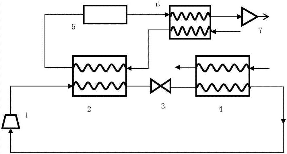
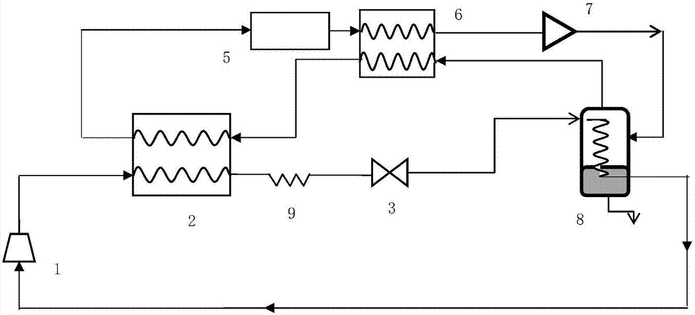
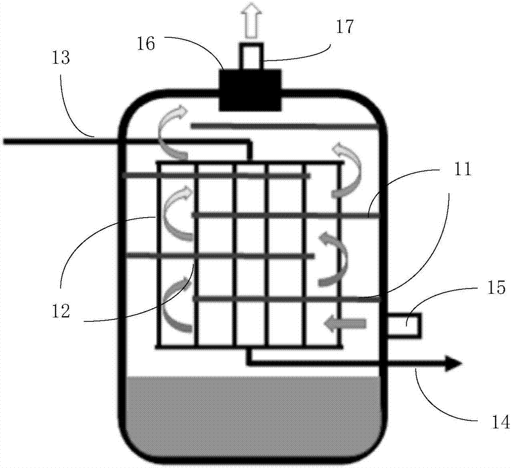
The invention provides a heat pump drying system which comprises a compressor, a condenser, a throttling component, an evaporator, a drying chamber, a backheating heat exchanger and a draught fan. Anoutlet of the compressor is connected with a hot end inlet of the condenser, a hot end outlet of the condenser is connected with a cold end inlet of the evaporator through the throttling component, and a cold end outlet of the evaporator is connected with an inlet of the compressor; a cold end inlet of the backheating heat exchanger inputs air acted by the draught fan, a cold end outlet of the backheating heat exchanger is connected with a cold end inlet of the condenser, a cold end outlet of the condenser is connected with an inlet of the drying chamber, an outlet of the drying chamber is connected with a hot end inlet of the backheating heat exchanger, a hot end outlet of the backheating heat exchanger is connected with an inlet of the draught fan, and an outlet of the draught fan is communicated with the outside. By means of the heat pump drying system, the backheating heat exchanger is used for achieving temperature recovering of air discharged from the drying chamber, the temperature of air entering the cold end evaporator is decreased, the temperature of air entering the hot end condenser is increased, the heat exchange temperature difference can be effectively reduced, coldand heat end heat exchange is improved, and the system efficiency is improved.

Description

technical field [0001] The invention relates to the field of drying technology, in particular to a high-efficiency heat pump drying system that uses heat recovery to fully recover energy. Background technique [0002] Drying technology has a very wide range of applications in many industries. However, the traditional drying process consumes a lot of energy. In developed countries, about 10% to 20% of the fuel is used in the drying process. Heat pump technology has been introduced into the drying industry due to its advantages of high efficiency, energy saving, low cost, and no pollution to the environment. At the same time, it can achieve accurate and independent control of temperature, humidity, and air velocity. It has been widely used in wood, seeds, tobacco, and textiles. , laundry and other industries. [0003] Chinese patent CN 103827385 A discloses a dryer using a heat pump, which obtains heat from the condenser at the high temperature end, recovers part of the heat...

Claims


Application Information

Patent Timeline
IPC IPC(8): F26B21/00F25B30/02F25B41/06F25B41/30
CPCF25B30/02F26B21/001F25B41/30
Inventor 李天张建平
Owner 北京恒泰盈创科技发展有限公司
Why Eureka
Try Eureka