Synchronous rectification controller and synchronous rectification control method

A synchronous rectification and controller technology, used in control/regulation systems, DC power input conversion to DC power output, instruments, etc., can solve the problem of long delays in turn-on and turn-off of synchronous rectifier MOS transistors, improved system efficiency, and reduced efficiency and other problems, to achieve the effect of speeding up the turn-on and turn-off speed, reducing the loss, and reducing the loss

Active Publication Date: 2018-04-27
成都启臣微电子股份有限公司
View PDF3 Cites 16 Cited by
  • Summary
  • Abstract
  • Description
  • Claims
  • Application Information

AI Technical Summary

Problems solved by technology

[0004] However, since the synchronous rectification MOS transistor is used in a high-current system, the area of ​​the synchronous rectification MOS transistor is large and the gate parasitic capacitance is large
The current synchronous rectification control method is generally a fixed voltage shutdown mode, which will cause inappropriate current shutdown timing, or difficulties in matching or selecting synchronous rectification MOS tubes, and the tu

Method used


Image

  • Synchronous rectification controller and synchronous rectification control method
  • Synchronous rectification controller and synchronous rectification control method
  • Synchronous rectification controller and synchronous rectification control method

Examples


Example Embodiment

[0019] The technical solutions in the embodiments of the present invention will be clearly and completely described below in conjunction with the accompanying drawings in the embodiments of the present invention. Obviously, the described embodiments are only a part of the embodiments of the present invention, rather than all the embodiments. Based on the embodiments of the present invention, all other embodiments obtained by those of ordinary skill in the art without creative work shall fall within the protection scope of the present invention.
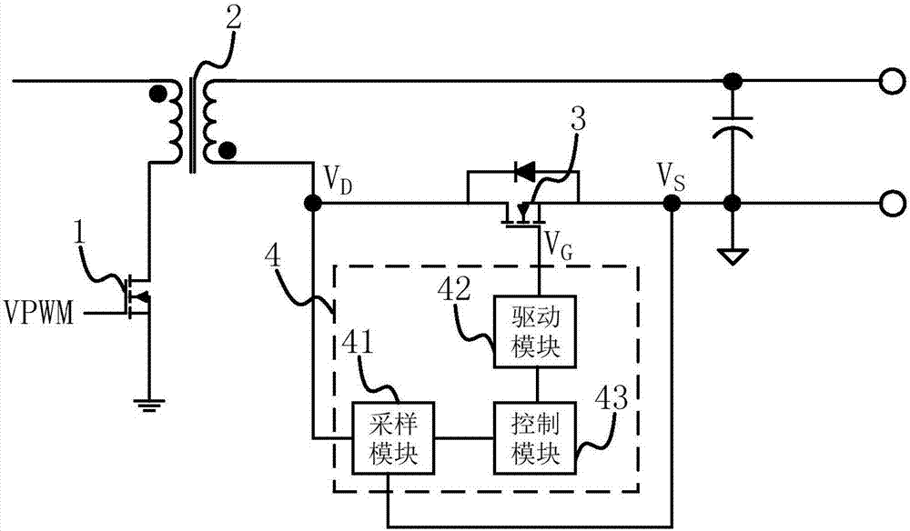
[0020] Refer to figure 1 , Is a schematic diagram of a power supply system using the synchronous rectification controller of the embodiment of the present invention. In this embodiment, the power supply system includes a power switch tube 1, a transformer 2 and a synchronous rectifier MOS tube 3. The synchronous rectification controller 4 includes a sampling module 41, a driving module 42 and a control module 43.

[0021] The sampling mod...


PUM


Abstract

The invention discloses a synchronous rectification controller and a synchronous rectification control method. The controller comprises a sampling module, a driving module and a control module, wherein the sampling module is used for sampling a source voltage and a drain voltage of a synchronous rectification metal-oxide-semiconductor (MOS) tube and acquiring a voltage difference value between thesource voltage and the drain voltage, the driving module is used for adjusting a grid voltage of the tube, and the control module is used for comparing the voltage difference value, a first thresholdvalue and a second threshold value, controlling the driving module to adjust the grid voltage of the tube to maximum output voltage when the voltage difference value is smaller than the first threshold value, controlling the driving module to adjust the grid voltage of the tube to change between 0 and the maximum output voltage when the voltage difference value is larger than the first thresholdvalue and smaller than the second threshold value so that the voltage difference value is adjusted to be equal to the first threshold value, and controlling the driving module to adjust the grid voltage of the tube to 0 when the voltage difference value is larger than the second threshold value. By the controller, the switch-on and switch-off speed of the synchronous rectification MOS tube can beincreased, so that the efficiency is obviously improved, and the loss is obviously reduced.

Description

technical field [0001] The invention relates to the field of basic electronic circuits, in particular to a synchronous rectification controller and a synchronous rectification control method. Background technique [0002] Due to the gradual increase in the requirements for energy conservation and environmental protection, countries have also formulated higher energy efficiency standards to regulate the efficiency and energy consumption of power supply products and household appliances. However, in some high-current output applications, the general flyback topology application The rectifier diodes used have problems such as large conduction voltage drop, unsatisfactory withstand voltage, and large parasitic resistance, which lead to failure to meet the requirements of energy efficiency standards. [0003] The synchronous rectification circuit is specially applied for high current output conditions. It uses synchronous rectification MOS tubes to replace the rectifier diodes in...

Claims


Application Information

Patent Timeline
IPC IPC(8): H02M3/335
CPCH02M3/33592H02M1/0054Y02B70/10
Inventor 许刚颍唐波吴强向磊马强
Owner 成都启臣微电子股份有限公司
Why Eureka
Try Eureka