
Device for gasifying and reducing high-temperature oil gas, removing dust, cooling, reducing tar, refining and separating

A separation device, oil and gas technology, applied in gas dust removal, combustible gas purification, combustible gas purification/reconstruction, etc., can solve the problem of low dust removal efficiency, and achieve the effects of simple structure, convenient overall installation, and low wear and tear.

Pending Publication Date: 2018-05-01
浙江天禄环境科技有限公司
View PDF3 Cites 2 Cited by
  • Summary
  • Abstract
  • Description
  • Claims
  • Application Information

AI Technical Summary

Problems solved by technology

It should be said that the above several devices have a certain dust removal effect, and they are used more now, but a single device often has a low dust removal efficiency, and a certain amount of dust particles and heavy tar enter the follow-up equipment, giving follow-up light The quality of high-quality tar, the quality of coke oven gas, and pipeline blockage have a great impact. Often the dust removal effect is good or bad, and the removal rate of heavy tar directly determines the quality and production efficiency of the company's products.
[0006] Therefore, it has not been reported that the high-temperature oil and gas of dust removal and heavy tar reduction and the oil sludge composed of coal dust and heavy tar are catalytically cracked again, gasification reduction and other chemical methods to increase the added value of the product have not yet been reported.

Method used


Image

  • Device for gasifying and reducing high-temperature oil gas, removing dust, cooling, reducing tar, refining and separating
  • Device for gasifying and reducing high-temperature oil gas, removing dust, cooling, reducing tar, refining and separating
  • Device for gasifying and reducing high-temperature oil gas, removing dust, cooling, reducing tar, refining and separating

Examples


Embodiment Construction

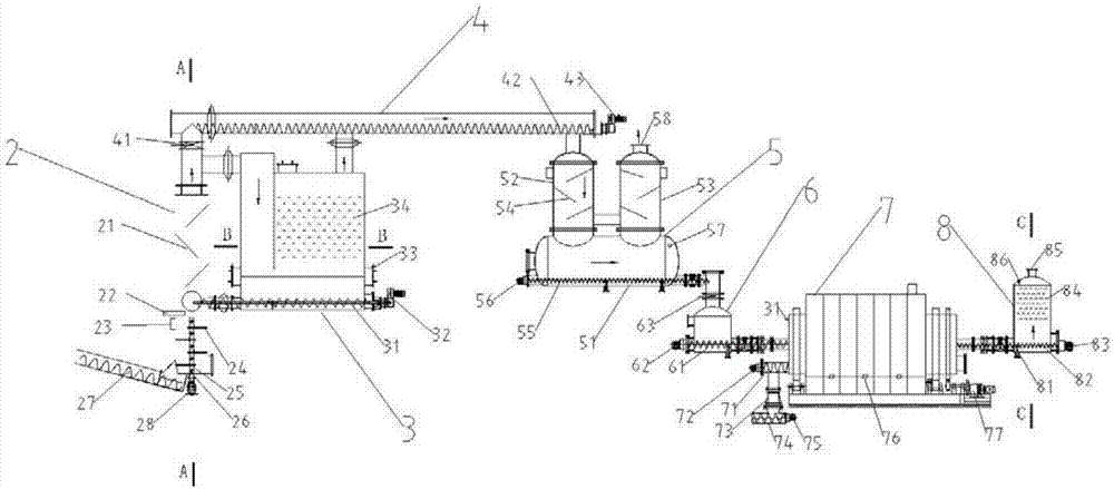
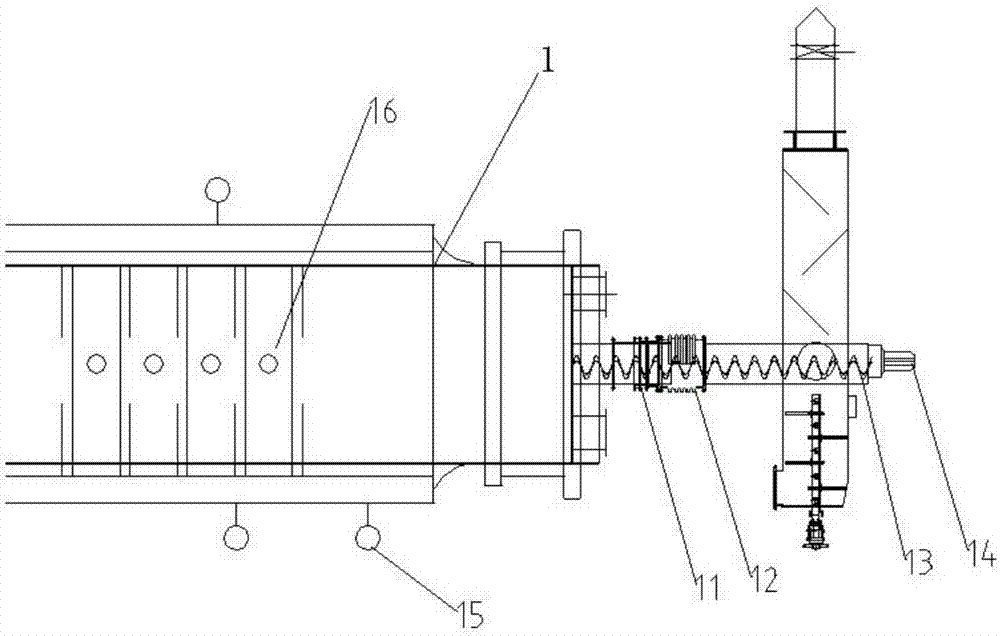
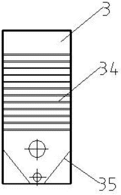
[0088] Such as Figure 1-Figure 4 A gasification reduction high-temperature oil gas dedusting, cooling, decoking and refining separation device is shown, which includes a reaction kettle 1 connected in sequence, a first dust collector 2, a primary filter 3, a circular pipe 4, a secondary filter 5, Storage box 6, refining kettle 7 and second dust collector 8, wherein:

[0089] Reactor 1 is used for dry distillation and gasification reduction of coal; a wireless temperature sensor 16 is installed inside, and a first screw 13 and a first motor 14 are installed at the outlet; the first dust collector 2 removes a large amount of dust entrained by high-temperature oil and gas; It is connected with the reaction kettle 1 through a dynamic and static sealing device 11, including a first baffle plate 21 installed above, a rotating shaft 25 with a stirring blade 24 and a second motor 26 installed below, and a third screw for discharging materials is installed at the bottom. 27 and the t...


PUM


Abstract

The invention discloses a device for gasifying and reducing high-temperature oil gas, removing dust, cooling, reducing tar, refining and separating. The device comprises a reaction kettle, a first dust remover, a primary filter, a secondary filter, a refining kettle and a second dust remover which are connected sequentially, wherein the reaction kettle is used for performing dry distillation and gasification reduction on coal; the first dust remover is used for removing a large amount of the dust entrained by the high-temperature oil gas; the primary filter is used for continuously removing the dust from the high-temperature oil gas and reducing heavy tar content; the secondary filter is used for continuously cooling the heavy tar and removing coal dust from the oil gas; the refining kettle is used for further performing gasification and reduction on fatlute through heating catalysis; and the second dust remover is used for performing heating catalysis and gasification-reduction on thegenerated oil gas to further remove the dust. The device has high removal rate of the dust and the heavy tar, can automatically lock gas, can continuously discharge materials, further utilizes the fatlute, increases the additional value of products, improves the quality of products, simplifies the subsequent separation equipment, can realize continuous operation and truly realizes industrializedmass production.

Description

technical field [0001] The invention belongs to the technical field of energy development and environmental protection, and in particular relates to a gasification reduction high-temperature oil gas dedusting cooling coke reduction and refining separation device. Background technique [0002] Coal dry distillation (that is, coal coking) refers to the process in which coal (coal) is heated in the absence of air to generate gas, tar, crude benzene and coke by pyrolysis. The large-scale use of coal coking technology in industrial production began in the 18th century to produce coke needed for ironmaking. In view of the combustion characteristics of coal itself, coal coking needs to be completed under the condition of being isolated from the air, so as to avoid the direct contact between the oxygen in the air and the hot coal during the coking process to cause combustion or oxidation reaction, so as to efficiently convert coal into coke the goal of. After long-term continuous ...

Claims


Application Information

Patent Timeline
IPC IPC(8): C10K1/02C10G11/00C10B53/04
CPCC10B53/04C10G11/00C10K1/02C10K1/022C10K1/024
Inventor 吕彬峰潘建波冯振蕫金飞伟
Owner 浙江天禄环境科技有限公司
Learn More