Composite material flywheel rotor and manufacturing method thereof

A flywheel rotor, composite material technology, applied in the direction of controlling mechanical energy, electrical components, electromechanical devices, etc., can solve the problems of loss of magnetism of permanent magnet blocks, large rotor heat generation, large eddy current loss, etc., to improve structural strength and alleviate heat dissipation. Difficulty, the effect of reducing eddy current loss

Pending Publication Date: 2018-05-01
DUNSHI MAGNETIC ENERGY TECH
View PDF4 Cites 3 Cited by
  • Summary
  • Abstract
  • Description
  • Claims
  • Application Information

AI Technical Summary

Problems solved by technology

[0003] The technical problem to be solved by the present invention is that the existing high-speed flywheel structure will produce large eddy current loss at high speed, the rotor w

Method used


Image

  • Composite material flywheel rotor and manufacturing method thereof
  • Composite material flywheel rotor and manufacturing method thereof

Examples


Embodiment Construction

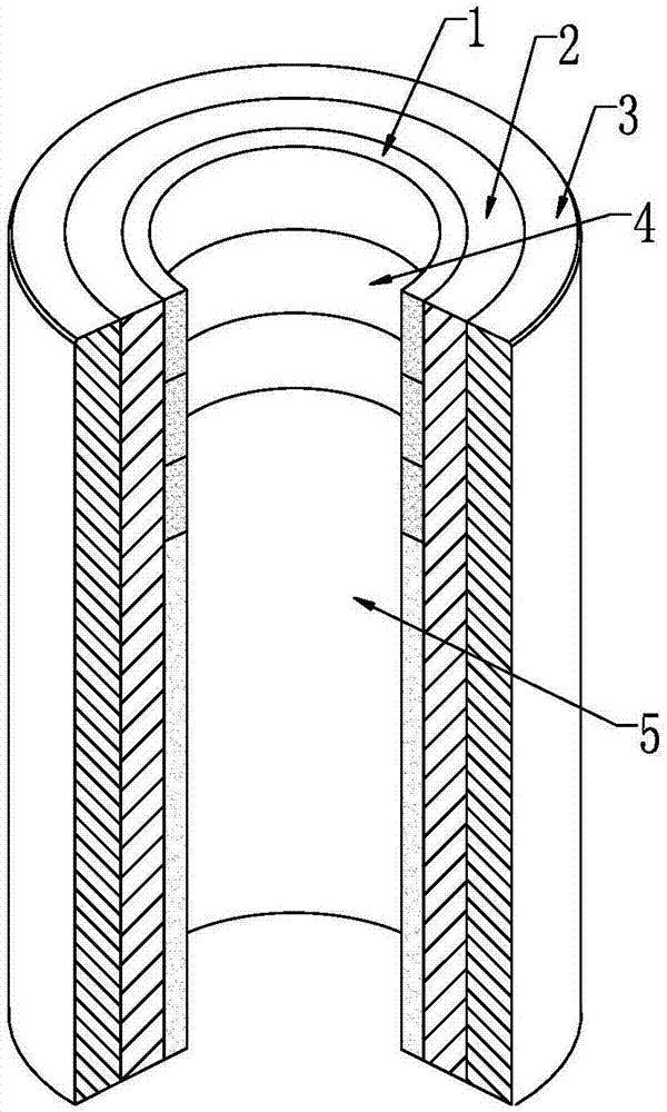
[0023] Aiming at the problems in the prior art, the present invention provides a flywheel rotor made of composite material. The purpose is to replace the traditional metal material with composite material, and make the flywheel rotor have a higher rotational speed by using a special processing technology. At the same time, the epoxy resin is used to wrap the magnetic powder particles, and the magnetic poles are made by co-winding with the reinforcing fiber material, replacing the traditional surface-mounted permanent magnets, so as to reduce the eddy current loss.

[0024] Below in conjunction with accompanying drawing the invention is described in detail, figure 1 A structural diagram of the rotor of the present invention is shown. A composite material flywheel rotor has a hollow cylindrical structure as a whole, its inner layer is a magnetic powder fiber layer, and the outer side of the magnetic powder fiber layer is a composite material layer formed by winding multiple comp...


PUM


Abstract

The invention provides a composite material flywheel rotor, which is formed by winding a magnetic powder fiber layer on the inner layer and a composite fiber layer on the outer layer; the outer side of the magnetic powder fiber layer is a composite material layer which is formed by sequentially winding a plurality of composite fiber materials; an upper magnetic pole and a lower magnetic pole withdifferent structures are formed after the magnetic powder fiber layer is magnetized, the upper half part of the magnetic pole is used as a rotor part of a radial magnetic suspension bearing, and the lower half part of the magnetic pole is used as an excitation magnetic pole of the motor. The invention further provides a manufacturing method of the composite material flywheel rotor, which comprisesthe following steps: 1) respectively manufacturing and winding the magnetic powder fiber layer and the other composite layers; 2) respectively magnetizing the upper portion and the lower portion of the magnetic powder fiber layer, using a cylindrical tire shaft when the composite layer is wound, and adopting a bidirectional heating method for curing while winding. According to the composite material flywheel rotor and the manufacturing method in the invention, the circumferential stress concentration problem and the problem of large heating amount loss of the rotor eddy current are solved; and the rotor can be used for manufacturing the higher-rotation-speed flywheel energy storage device.

Description

technical field [0001] The invention belongs to the field of high-speed motors, and relates to a high-speed flywheel rotor made of composite materials integrating a motor / generator permanent magnet rotor and an energy storage flywheel and a manufacturing method of the flywheel rotor. Background technique [0002] A flywheel is a device that uses the inertia of a rotating object to store energy. Compared with energy storage devices such as batteries, capacitors, and inductors, it has the advantages of large energy storage capacity, long service life, high efficiency, multiple continuous charge and discharge, clean and pollution-free, etc. Flywheel energy storage is currently suitable for grid frequency modulation, small island grid peak shaving, grid security and stability control, power quality management, vehicle regenerative braking, and high-power pulse power supplies. At present, most flywheels still use metal hubs, and the processing technology is mature. However, com...

Claims


Application Information

Patent Timeline
IPC IPC(8): H02K7/02H02J3/30
CPCH02J3/30H02K7/025Y02E60/16
Inventor 张建平焦志青李胜飞唐英伟温海平赵思锋王大杰于金龙
Owner DUNSHI MAGNETIC ENERGY TECH
Why Eureka
Try Eureka