Power factor correction device based on novel transformer and inductor

A power factor correction and transformer technology, which is applied in the direction of output power conversion devices, electrical components, high-efficiency power electronic conversion, etc., can solve the problems of three-phase power factor correction device circuit structure, working mechanism and control complexity, large wire size, etc. , to achieve the effect of good parameter repeatability, short heat channel distance and good heat conduction

Inactive Publication Date: 2018-05-01
NANJING UNIV OF SCI & TECH
View PDF6 Cites 0 Cited by
  • Summary
  • Abstract
  • Description
  • Claims
  • Application Information

AI Technical Summary

Problems solved by technology

[0002] The three-phase power factor correction device is still in the development stage due to its complicated circuit structure, working mechanism and control.
However, the wire size used to meet this requirement may be larger and heavier than desired or needed

Method used


Image

  • Power factor correction device based on novel transformer and inductor
  • Power factor correction device based on novel transformer and inductor
  • Power factor correction device based on novel transformer and inductor

Examples


Embodiment Construction

[0027] 1. Main circuit

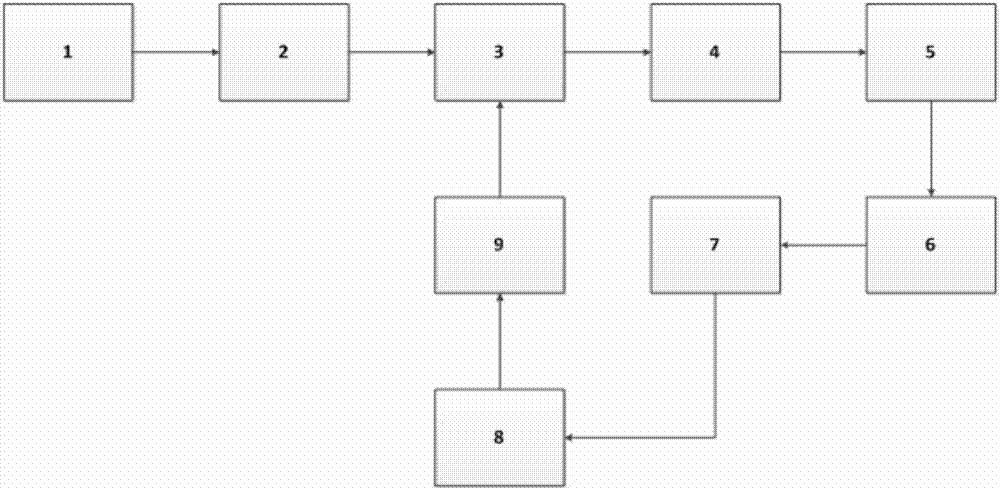
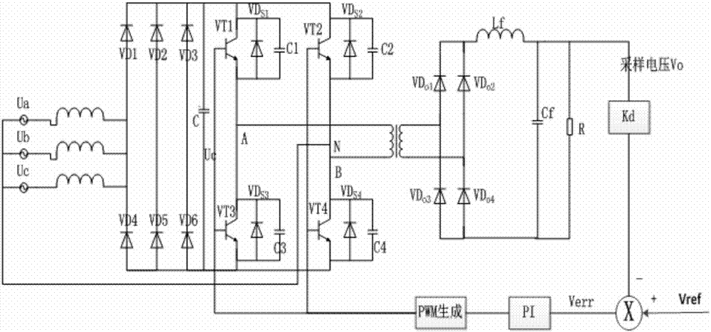
[0028] The main circuit includes: three-phase three-wire AC source, three-phase input rectification, phase-shifting bridge, high-frequency transformer, output filter rectification.

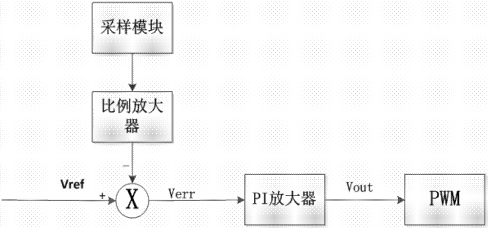
[0029] Its working principle: the present invention adopts an improved three-phase single-stage APFC circuit based on a full-bridge topology. Utilizing the switches of VT2 and VT4 and the charging and discharging energy of La, Lb and Lc can not only realize power factor correction, but also improve the soft switching of VT2 and VT4.

[0030] 2. Working process

[0031] Take the 0≤ωt≤π / 3 stage as an example for analysis. The circuit has 6 working modes in one switching cycle, and the working waveform is as follows Figure 4 shown.

[0032] Mode 1(t 0 -t 1 ): The switch VT3 has been turned on, at the time t0 VT 2 conduction, VT 1 , VT 4 due. A, C phase current i Ls i Lc Approximately linearly increasing from zero, the B-phase current begins to feed the filter cap...


PUM


Abstract

The invention discloses a power factor correction device based on novel transformer and inductor, comprising a three-phase and three-wire input power supply (1), a three-phase input rectification part(2), a phase shift bridge (3), a high-frequency transformer (4), an output filtering rectification circuit (5), a sampling circuit (6), a proportional amplifier (7), a PI amplifier (8), and a PWM generator (9). The power factor correction device is characterized in that the three-phase and three-wire input power supply (1) adopts an AC inductor; the high-frequency transformer (4) adopts a plane transformer; the output filtering rectification circuit (5) adopts a magnetic core DC inductor having an air gap. The invention is advantageous in that high current density is provided in that currentdensity is high because the leads of the plane transformer are actually plane conductors; efficiency is as high as 98%-99%; leakage inductance is low, which is 0.2% of the primary inductance; thermalconduction is good, heat passage distance is short and temperature rise is low; EMI radiation is low, and good magnetic core shielding can reduce the radiation to a quite low level.

Description

technical field [0001] The invention belongs to the power factor correction in the switching power supply, and is applied in the aerospace field, scientific instruments, solar battery arrays and the like. Background technique [0002] The three-phase power factor correction device is still in the development stage because of its complicated circuit structure, working mechanism and control. [0003] In particular, the transformers are basically ordinary transformers, and the voltage spikes seen at one time in ordinary transformers are caused by leakage inductance. To design a converter transformer with minimum leakage inductance, there must be a minimum distance between the primary and secondary. [0004] Currently, in the design of three-phase power factor correction devices, various methods are usually adopted to obtain a suitable inductor design. For example, in many cases a rule of thumb for scheduling current densities is used. Set 200A / cm 2 (100CM / A) can get a very ...

Claims


Application Information

Patent Timeline
Patent Type & Authority Applications(China)
IPC IPC(8): H02M1/42
CPCH02M1/4241Y02B70/10
Inventor 李强韩业华徐海瑞金天陆荣
Owner NANJING UNIV OF SCI & TECH
Why Eureka
Try Eureka