Biological film-film biological coupling sewage treatment device

A sewage treatment system and sewage technology, applied in the direction of biological water/sewage treatment, sustainable biological treatment, water/sludge/sewage treatment, etc., can solve the problems of sewage treatment methods that need to be improved, so as to improve the efficiency of sewage treatment, increase the Large contact area, effect from a wide range of sources

Pending Publication Date: 2018-05-04
TSINGHUA UNIV
View PDF6 Cites 4 Cited by
  • Summary
  • Abstract
  • Description
  • Claims
  • Application Information

AI Technical Summary

Problems solved by technology

[0003] However, the current sewage treatment syste...

Method used


Image

  • Biological film-film biological coupling sewage treatment device
  • Biological film-film biological coupling sewage treatment device
  • Biological film-film biological coupling sewage treatment device

Examples


Embodiment 1

[0085] Can refer to Figure 7 process shown.

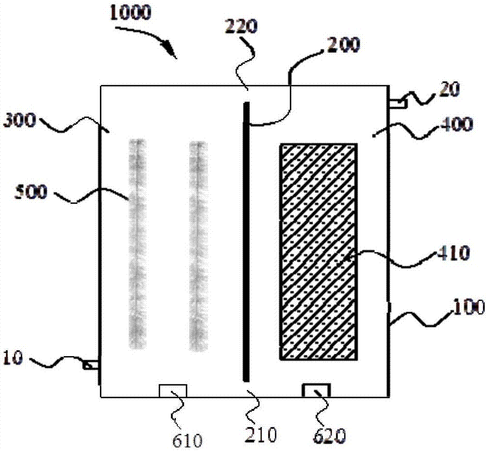
[0086] (1) Pump the sewage in the water inlet tank 700 to the water inlet 10 at the bottom of the housing 100 through the water inlet pump 710, and the water inlet flow rate is 0.2m 3 / h.

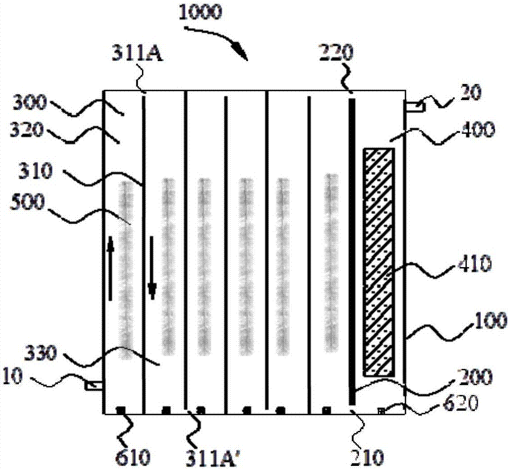
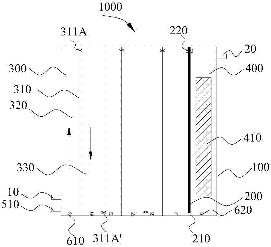
[0087] (2) The sewage flows through the upflow zone 320 and the downflow zone 330 in sequence. There is a perforated aeration pipeline 630 at the bottom of the upflow zone 320, and the air outlet 610 at the bottom of the upflow zone 320 is opened. The air-water lift force generated by aeration can push the water upward, and at the same time, the aeration can provide dissolved oxygen to the upflow zone 320 , when the water flow rises to the top of the upflow area 320, it can flow into the downflow area 330 through the water flow channel 311A, close the air outlet 610 at the bottom of the downflow area, and the water in the downflow area 330 flows to the bottom, and then passes through the water flow channel 311A ​​there 'Enter the next upflow...

Embodiment 2

[0093] Pump the sewage in the water inlet tank 700 to any auxiliary water inlet 80 on the housing 100 through the water inlet pump 710, and close the water flow path between the top of the first partition near the front end of the auxiliary water inlet 80 and the housing 100 311. Refer to Embodiment 1 for other operating modes. In this embodiment, the minimum hydraulic retention time of the sewage can be as low as 3 hours.

Embodiment 3

[0095] Close the aeration pipe 630 and the aeration ports 610 corresponding to the first two upflow areas 320, and close all the air outlets 610 of the downflow areas 330, and pass the sewage in the terminal downflow area 330 through the backflow outlet 30 through the backflow pump Return to the return water inlet 40, or directly return to the water inlet 10, and refer to Embodiment 1 for other operating modes. In this embodiment, the distribution of dissolved oxygen in the biological reaction space 300 is adjusted through the aeration pipeline 630, the aeration ports 610 corresponding to the first two upflow areas 320 are closed, and the air outlets 610 of all downflow areas are closed , the first two upflow zones 320 and all downflow zones 330 are in anaerobic / anoxic state, therefore, microbial anaerobic and denitrification reactions can occur in them; aeration in the upflow zone at the end of the biological reaction space 300 If the port 610 is kept open, the corresponding ...


PUM


Abstract

The invention discloses a biological film-film biological coupling sewage treatment device. The biological film-film biological coupling sewage treatment device specifically comprises a shell body, biological carrier filler and a membrane assembly, wherein a separation plate is arranged in the shell body; a biological reaction space and a membrane filtering space are limited in the shell body by the separation plate; a first water flow through hole is formed in the bottom of the separation plate; a water inlet is formed in one side, close to the biological reaction space, of the shell body; awater outlet is formed in the top of one side, close to the membrane filtering space, of the shell body; the biological carrier filler is arranged in the biological reaction space; an aeration openingis formed in the bottom of the biological reaction space; the membrane assembly is vertically arranged in the membrane filtering space; a membrane filtering aeration opening is formed in the bottom of the membrane filtering space. Therefore, the sewage treatment device disclosed by the invention not only has the advantages of impact load resistance, simple and compact structure, small occupied area, low sludge expansion ratio and, and output water has better quality and is more stable; furthermore, the membrane pollution can be reduced and the energy consumption and the operation cost are reduced.

Description

technical field [0001] The invention relates to the field of sewage treatment, in particular to a biofilm-membrane biological coupling sewage treatment device, and more specifically to a sewage treatment system and a sewage treatment method. Background technique [0002] With the continuous expansion of population size and the continuous development of social economy, the discharge of urban domestic sewage and industrial sewage also increases, and the load of sewage treatment continues to increase, which requires higher and higher levels of sewage treatment. In recent years, the further treatment of sewage through bioreactors has become the main trend. Microbes can remove soluble and colloidal biodegradable organic matter, phosphorus, nitrogen, etc. in sewage, and have the advantages of high efficiency, low energy consumption, low cost, simple operation, and mild reaction conditions. [0003] However, the current sewage treatment system and sewage treatment methods still ne...

Claims


Application Information

Patent Timeline
IPC IPC(8): C02F3/12C02F3/34C02F3/00
CPCC02F3/00C02F3/1236C02F3/1268C02F3/34Y02W10/10
Inventor 张潇源魏卡佳黄霞曹效鑫梁鹏
Owner TSINGHUA UNIV
Why Eureka
Try Eureka